Batteries can emit explosive gases. To reduce the possibility of personal injury, always ventilate the compartment before servicing the batteries. To reduce the possibility of arcing, remove the negative (-) battery cable first and attach the negative (-) battery cable last.
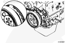
For 3.9 L and 5.9 L Engines without EGR, align the crankshaft speed indicator ring on the front of the crankshaft so that the unpunched area of the crankshaft speed indicator ring is at the 12-o’clock position. If both number 1 cylinder rocker levers are loose, move to the following steps. If both number 1 cylinder rocker levers are not loose, rotate the crankshaft 360 degrees.
NOTE: The TDC indicator is on the vibration damper/crankshaft speed indicator ring.
For all 4.5 L, 5.9 L engines with EGR, and 6.7 L engines, align the vibration damper/crankshaft speed indicator ring so that the TDC indicator is at the 12-o’clock position. If both number 1 cylinder rocker levers are loose, move to the following steps. If both number 1 cylinder rocker levers are not loose, rotate the crankshaft 360 degrees.
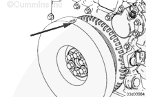
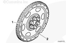
NOTE: If no TDC mark is present on either the vibration damper or the crankshaft speed indicator ring, align the large gap in the crankshaft speed indicator ring to the 5-o’clock position (2). The dowel pin could also be visible in the 9-o’clock position (1). Check that both number 1 cylinder rocker levers are loose. If they are not loose, rotate the crankshaft 360 degrees and recheck.
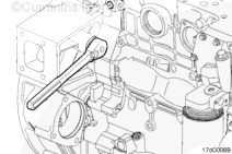
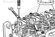
NOTE: The clearance is correct when some resistance is “felt” when the feeler gauge is slipped between the crosshead and the rocker lever socket.
Measure lash by inserting a feeler gauge between the crosshead and the rocker lever socket. If the lash measurement is out of specification, loosen the locknut, and adjust the lash to nominal specifications.
Batteries can emit explosive gases. To reduce the possibility of personal injury, always ventilate the compartment before servicing the batteries. To reduce the possibility of arcing, remove the negative (-) battery cable first and attach the negative (-) battery cable last.
Hello, I'm Jack, a diesel engine fan and a blogger. I write about how to fix and improve diesel engines, from cars to trucks to generators. I also review the newest models and innovations in the diesel market. If you are interested in learning more about diesel engines, check out my blog and leave your feedback.
View all posts by Jack
 WARNING


;)
;)
;)
;)
;)
;)
;)
;)
;)
;)
;)
;)
;)
;)