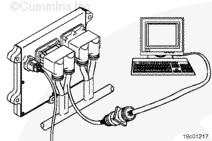
Connect INSITE™ electronic service tool to the vehicle datalink.
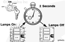
Turn the keyswitch to the ON position.
Select the Monitor Mode on INSITE™ electronic service tool. INSITE™ electronic service tool must be able to communicate with the electronic control module (ECM). If the ECM will not communicate with INSITE™ electronic service tool, refer to the ECM – No Communication symptom tree in Section TF.
Record the values of ECM Distance Offset, ECM Time Offset, Engine Distance Offset, and Engine Time Offset prior to replacement or calibration of the ECM. These parameters can be found in the Trip Information section of Features and Parameters.
NOTE: Record all programmable parameters, features, and calibration information from the old ECM before disconnecting the harness connectors. This information will be needed to program the new ECM.
Batteries can emit explosive gases. To reduce the possibility of personal injury, always ventilate the compartment before servicing the batteries. To reduce the possibility of arcing, remove the negative (-) battery cable first and attach the negative (-) battery cable last.
Disconnect the battery connections. Refer to Procedure 013-009 in the ISM, ISMe and QSM11 Service Manual, Bulletin 3666322, or the Signature, ISX and QSX15 Service Manual, Bulletin 3666239.
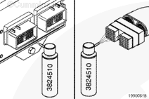
Disconnect the ECM power harness (1), engine harness (2), and original equipment manufacturer (OEM) harness (3) connectors from the ECM if they are not already removed.
Do not blow compressed air into the ECM ports or connectors. Compressed air can contain moisture due to condensation.
Use quick-dry electrical contact cleaner, Part Number 3824510, to remove all dirt and moisture from the ECM connector ports and the harness connectors.
Connect the ECM power harness (1), engine harness (2), and OEM harness (3) connectors to the ECM. Tighten the connector capscrews to the ECM.
Torque Value: 3 n.m [27 in-lb]
NOTE: When an ECM is replaced, the new ECM must be calibrated. Refer to Procedure 019-032.
Adjust the values of ECM Distance Offset, ECM Time Offset, Engine Distance Offset, and Engine Time Offset after calibrating the ECM. These parameters can be found in the Trip Information section of Features and Parameters.
Batteries can emit explosive gases. To reduce the possibility of personal injury, always ventilate the compartment before servicing the batteries. To reduce the possibility of arcing, remove the negative (-) battery cable first and attach the negative (-) battery cable last.
Connect the battery connections. Refer to Procedure 013-009 in the ISM, ISMe and QSM11 Service Manual, Bulletin 3666322, or the Signature, ISX and QSX15 Service Manual, Bulletin 3666239.
NOTE: When an ECM is replaced, the new ECM must be calibrated. Refer to Procedure 019-032.
Hello, I'm Jack, a diesel engine fan and a blogger. I write about how to fix and improve diesel engines, from cars to trucks to generators. I also review the newest models and innovations in the diesel market. If you are interested in learning more about diesel engines, check out my blog and leave your feedback.
View all posts by Jack


 WARNING
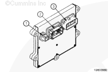
 CAUTION

;)
;)
;)
;)
;)
;)
;)
;)
;)
;)