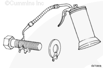
Batteries can emit explosive gases. To reduce the possibility of personal injury, always ventilate the compartment before servicing the batteries. To reduce the possibility of arcing, remove the negative (-) battery cable first and attach the negative (-) battery cable last.
Disconnect the batteries. Refer to the OEM service manual.
When using solvents, acids, or alkaline materials for cleaning, follow the manufacturer’s recommendations for use. Wear goggles and protective clothing to reduce the possibility of personal injury.
WARNING
Wear appropriate eye and face protection when using compressed air. Flying debris and dirt can cause personal injury.
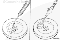
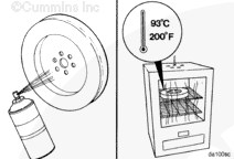
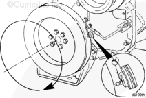
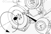
Clean the vibration damper with solvent and dry with compressed air.
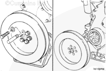
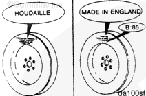
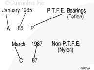
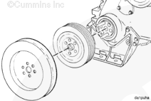
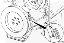
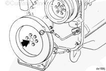
Determine if the vibration damper is a cast type or fabricated type.
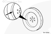
Fabrication vibration dampers are the most common type and can be identified by a weld bead on the front center section of the damper where the housing joins the mounting flange.
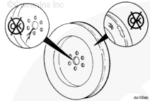
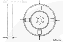
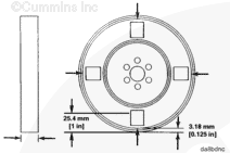
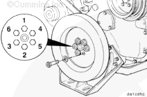
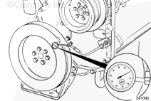
Measure and record the thickness at two points on each of the four locations.
Measure the thickness at 3.18 mm [0.125 in] from the outer lip.
Measure the thickness at 25.4 mm [1.0 in] from the outer lip.
This procedure will result in a total of eight measurements.
If the variations between any of the eight measurements exceeds 0.25 mm [0.010 in], or if the thickness at any point exceeds the maximum thickness dimensions indicated below in the table, the damper must be replaced.
Engine Model
Housing Type
Bearing Material
Maximum Thickness
NT
Cast
Teflon and nylon
39.37 mm [1.550 in]
NT
Fabricated
Nylon
39.88 mm [1.570 in]
NT
Fabricated
Teflon
39.62 mm [1.560 in]
NT and N14
Cast
Teflon and nylon
44.20 mm [1.740 in]
NT and N14
Fabricated
Teflon and nylon
44.24 mm [1.663 in]
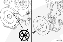
Replace the small vibration damper with a large vibration damper, if the small vibration damper fails inspection or the engine experienced a camshaft nose failure.
Batteries can emit explosive gases. To reduce the possibility of personal injury, always ventilate the compartment before servicing the batteries. To reduce the possibility of arcing, remove the negative (-) battery cable first and attach the negative (-) battery cable last.
Hello, I'm Jack, a diesel engine fan and a blogger. I write about how to fix and improve diesel engines, from cars to trucks to generators. I also review the newest models and innovations in the diesel market. If you are interested in learning more about diesel engines, check out my blog and leave your feedback.
View all posts by Jack

 WARNING


;)
;)
;)
;)
;)
;)
;)
;)
;)
;)
;)
;)
;)
;)
;)
;)
;)
;)
;)
;)
;)
;)
;)
;)
;)
;)
;)
;)
;)
;)
;)
;)
;)
;)
;)
;)
;)
;)
;)
;)