Batteries can emit explosive gases. To reduce the possibility of personal injury, always ventilate the compartment before servicing the batteries. To reduce the possibility of arcing, remove the negative (-) battery cable first and attach the negative (-) battery cable last.
NOTE: Read the entire procedure for overhead adjustment before attempting to perform this operation.
Valves and injectors must be correctly adjusted for the engine to operate efficiently. Valve and injector adjustment must be performed using the values listed in this section.
CELECT™ Plus Valve and Injector Adjustment Values
CELECT™ Plus Injector Adjustment: Bottom plunger, release, and bottom timing plunger. Back out two flats (120 degrees).
The preferred method of performing normal valve and step timing control (STC) injector overhead adjustment is to use the outer base circle (OBC) method, where the crush of the injector plunger to cup is set by tightening the injector rocker lever adjusting screw to a prescribed torque. If the STC injectors have been removed for cleaning and calibration, or if new ReCon injectors are being installed, use the OBC overhead set procedure.
NOTE: After an engine rebuild or any major repair where the injector setting must be disturbed, set all the valves and injectors.
CELECT™ Plus injectors will provide acceptable engine performance with lash (OBC) anywhere from 0.51 to 2.04 mm [0.020 to 0.080 in]. The procedure for CELECT™ Plus injector reset will produce lash between 0.51 and 0.74 mm [0.020 and 0.029 in]. Under normal operation, there is never a reason to adjust CELECT™ Plus injectors for excessive lash between scheduled maintenance intervals.
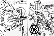
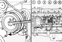
Do not pull or pry on the fan to manually rotate the engine. To do so can damage the fan blades. Damaged fan blades can cause premature fan failures which can result in serious personal injury or property damage.
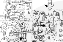
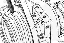
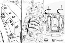
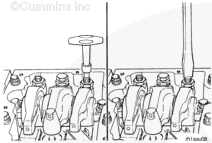
The valve set marks are located on the accessory drive pulley. The marks align with a pointer on the gear cover.
Use the accessory drive shaft to rotate the crankshaft.
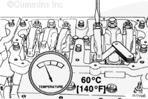
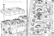
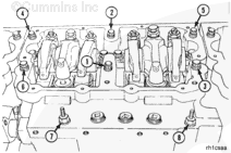
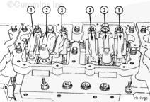
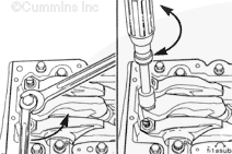
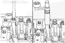
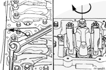
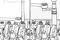
Each cylinder has three rocker levers. The rocker lever nearest to the center of the housing is the intake lever.
Exhaust rocker lever (1)
Injector rocker lever (2)
Intake rocker lever (3)
The two levers closest to the center of each rocker housing are the intake rocker levers. The two levers closest to the ends of the rocker housing are the exhaust levers.
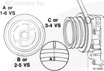
Rotate the accessory drive in the direction of engine rotation. The accessory drive will rotate clockwise , on a right hand engine, when looking at the front of the engine. Align the “A” or “1-6 VS” mark on the accessory drive pulley with the pointer on the gear cover.
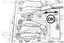
Check the valve rocker levers on cylinder number 1 to see if both valves are closed.
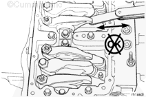
NOTE: Both valves are closed when both rocker levers are loose and can be moved from side to side. If both valves are not closed, rotate the accessory drive one complete revolution; and align the “A” mark with the pointer again.
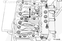
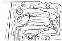
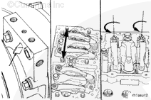
If the valve rocker lever adjusting screws have been loosened and not yet adjusted, watch the valve push tubes as the engine rolls upon the “A” mark. Both valve push tubes will have moved to the downward (valve closed) position if the engine is on the correct stroke.
When using solvents, acids, or alkaline materials for cleaning, follow the manufacturer’s recommendations for use. Wear goggles and protective clothing to reduce the possibility of personal injury.
WARNING
Some solvents are flammable and toxic. Read the manufacturer’s instructions before using.
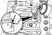
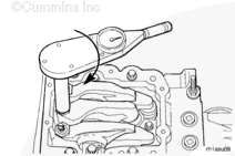
Clean the timing plunger to remove the varnish from the top edge.
Apply a non-chlorinated carburetor cleaner (Pyroil or equivalent) using a narrow bore orifice or extension tube of 2.0 mm [0.79 in] maximum outside diameter, into the injector weep hole.
If the entire overhead is to be reset, every injector is to be sprayed at this time.
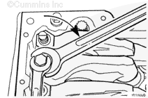
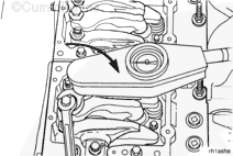
Loosen the injector adjusting screw lock nut on cylinder number 1. Bottom the injector timing plunger by tightening and loosening the adjusting screw three or four times to remove the fuel.
When removing the excess fuel, do not apply crush to the injector timing plunger by further tightening the adjusting screw after the plunger is bottomed.
Do not apply crush to the injector timing plunger by further tightening the adjusting screw. Doing so will result in an incorrect injector lash setting and can cause excessive injection train wear.
Tighten the adjusting screw on the injector rocker lever until the timing plunger just touches bottom.
After bottoming the CELECT™ Plus injector timing plunger, make certain to back out the adjusting screw two flats (120 degrees) or damage to the injector will result.
Back out the adjusting screw on the injector rocker lever two flats (120 degrees).
Two flats will provide 0.56 mm [0.022 in] lash. The specification is 0.50 to 0.74 mm [0.020 to 0.029 in] lash.
After setting the injector on a given cylinder, set the valves on the same cylinder.
With the “A” set mark aligned with the pointer on the gear cover and both valves closed on cylinder number 1, loosen the lock nuts on the intake and the exhaust valve adjusting screws.
Two different methods for establishing valve lash clearance are described below. Either method can be used; however, the torque wrench method has proven to be the most consistent.
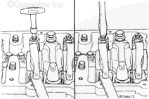
Torque Wrench Method: Use the inch pound torque wrench, Part Number 3376592, and tighten the adjusting screw.
Torque Value: 0.68 n.m [5 in-lb]
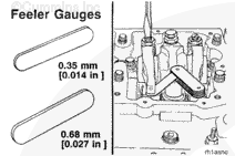
Feel Method: Tighten the adjusting screw until a slight drag is felt on the feeler gauge.
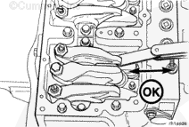
After tightening the lock nut to the correct torque value, check to make sure the feeler gauge will slide backward and forward between the crosshead and the rocker lever with only a slight drag.
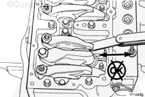
If using the feel method, attempt to insert a feeler gauge that is 0.03 mm [0.001 in] thicker between the crosshead and the rocker lever pad. The valve lash is not correct when a thicker feeler gauge will fit.
After adjusting the injector on cylinder number 1 and the valves on cylinder number 1, rotate the accessory drive and align the next valve set mark with the pointer.
An overtightened setting on the injector adjusting screw will produce increased stress on the injector train and the camshaft injector lobes, which can result in engine damage.
Use a dial type torque wrench to tighten the injector rocker lever adjusting screw to the specified torque. If the screw causes chattering during setting, repair the screw and lever as required.
Hold the torque wrench in a position that allows the direct view of the dial. This is to make certain that the reading on the dial is accurate.
With the “B” mark aligned with the pointer on the gear cover and both valves closed on cylinder number 5, loosen the locknuts on the intake and the exhaust valve adjusting screws.
Two different methods for establishing valve lash clearance are described below. Either method can be used: however, the torque wrench method has proven to be the most consistent.
Torque Wrench Method
Use the inch-pound torque wrench, Part Number 3376592 or equivalent, (normally used to set preload on STC injectors), and tighten the adjusting screw.
After tightening the locknut to the correct torque value, check to make sure the feeler gauge will slide backward and forward between the crosshead and the rocker lever with only a slight drag.
If using the feel method, attempt to insert a feeler gauge that is 0.03 mm [0.001 in] thicker between the crosshead and the rocker lever pad. The valve lash is not correct when a thicker feeler gauge will fit.
Hello, I'm Jack, a diesel engine fan and a blogger. I write about how to fix and improve diesel engines, from cars to trucks to generators. I also review the newest models and innovations in the diesel market. If you are interested in learning more about diesel engines, check out my blog and leave your feedback.
View all posts by Jack

 WARNING
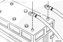


 CAUTION
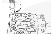


;)
;)
;)
;)
;)
;)
;)
;)
;)
;)
;)
;)
;)
;)
;)
;)
;)
;)
;)
;)
;)
;)
;)
;)
;)
;)
;)
;)
;)
;)
;)
;)
;)
;)
;)
;)
;)
;)
;)
;)
;)
;)
;)
;)
;)
;)
;)
;)
;)
;)
;)
;)
;)
;)
;)
;)
;)
;)
;)
;)
;)
;)
;)
;)
;)
;)