Test
TOC
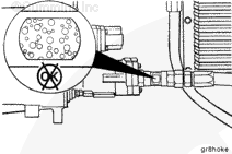
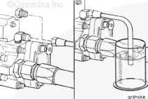
Sight Glass Method
Remove the fuel suction line.
Install a sight glass, Part Number 3375362, in the line.
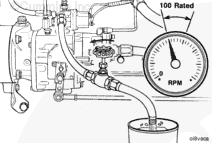
Operate the engine as in the previous section.
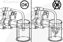
NOTE : A small air leak will have a “milky” appearance. A large air leak will look like bubbles in the fuel.
If an air leak is found, inspect the fuel lines, o-rings, and fittings for damage and loose connections.
Replace the damaged lines or tighten the loose connections.
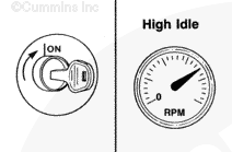
Operate the engine at high idle with no load and check the sight glass.
Tighten the hose connections and the fuel filter.
Check the drop tube in the fuel tank for damage.
Replace any damaged components as necessary.
Remove the sight glass and install the suction hose.
Test the engine again for other air leaks.
STC
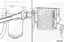
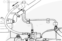
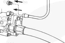
Remove the gear pump cooling drain line from the check valve and install a plug in the line.
Install a hose on the check valve and place the other end of the hose in a container.
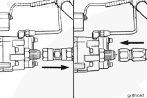
Remove the AFC air supply line from the air intake manifold or the compressor air tube and install a plug or a cap in the air manifold hole.
Apply air pressure to the AFC air supply line.
Measurements
kpa
psi
Air Pressure
172
25
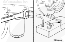
Remove the Compuchek™ fitting from the fuel shutoff valve, if equipped.
Install a fuel hose with a needle valve in it to the shutoff valve.
Close the needle valve and place the end of the hose in a bucket.
Operate the engine at high idle with
no
If air is entering the fuel pump suction line, bubbles will be visible in the container of fuel.
Tighten the hose connections and fuel filter.
Check the drop tube in the fuel tank for damage.
Remove the hose from the check valve elbow and the plug from the cooling drain line.
Install the drain line on the check valve.
Remove the fuel hose and needle valve from the fuel shutoff valve.
Install the Compuchek™ fitting in the fuel shutoff valve, if equipped.
Remove the plug or cap from the compressor air tube or the air intake manifold.
Install the AFC air supply line to the compressor air tube or the air intake manifold.
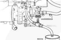
CELECT™ or CELECT™ Plus
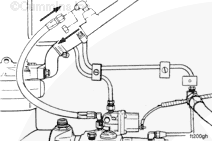
Remove the gear pump cooling drain line from the check valve and install a plug in the line.
Install a hose on the check valve and place the other end of the hose in a container.
Operate the engine at high idle with
no load.
If air is entering the fuel pump suction line, bubbles will be visible in the container of fuel.
If bubbles are visible, tighten the fuel supply pump inlet fitting.
Tighten the cooling plate inlet and outlet fittings.
Tighten the hose connections and the fuel filter.
Check the drop tube in the fuel tank for damage.
Remove the hose from the check valve elbow and the plug form the cooling drain line.
Install the drain line on the check valve.
Last Modified: 18-Oct-2011
Published by Jack
Hello, I'm Jack, a diesel engine fan and a blogger. I write about how to fix and improve diesel engines, from cars to trucks to generators. I also review the newest models and innovations in the diesel market. If you are interested in learning more about diesel engines, check out my blog and leave your feedback.
View all posts by Jack


;)
;)
;)
;)
;)
;)
;)
;)
;)
;)
;)
;)
;)
;)
;)
;)
;)
;)
;)
;)
;)
;)
;)
;)
;)
;)