When using solvents, acids, or alkaline materials for cleaning, follow the manufacturer’s recommendations for use. Wear goggles and protective clothing to reduce the possibility of personal injury.
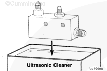
Use ultrasonic cleaners, Part Number 337665 or 3375001, and ultrasonic cleaner solution, Part Number 33750003, to clean the viscosity sensor.
When using solvents, acids, or alkaline materials for cleaning, follow the manufacturer’s recommendations for use. Wear goggles and protective clothing to reduce the possibility of personal injury.
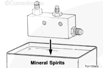
Use mineral spirits to neutralize the solution after cleaning.
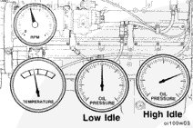
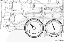
Operate the engine until the oil temperature stabilizes.
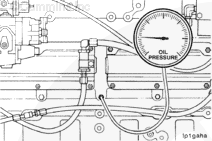
Observe the oil rifle pressure as the temperature of the oil is increasing. Compare the results with the values given in the Effect of Viscosity Sensor on Main Oil Rifle Pressure table.
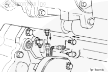
If the results do not agree with the table, verify that the base engine lubricating system is operating properly before removing the viscosity sensor.
Hello, I'm Jack, a diesel engine fan and a blogger. I write about how to fix and improve diesel engines, from cars to trucks to generators. I also review the newest models and innovations in the diesel market. If you are interested in learning more about diesel engines, check out my blog and leave your feedback.
View all posts by Jack


 WARNING


;)
;)
;)
;)
;)
;)
;)
;)
;)
;)
;)
;)
;)
;)
;)
;)
;)
;)
;)
;)
;)
;)
;)
;)
;)
;)
;)
;)
;)
;)
;)
;)
;)
;)
;)
;)