Batteries can emit explosive gases. To reduce the possibility of personal injury, always ventilate the compartment before servicing the batteries. To reduce the possibility of arcing, remove the negative (-) battery cable first and attach the negative (-) battery cable last.
Disconnect the batteries. Refer to the OEM service manual.
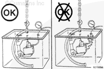
This component or assembly weighs greater than 23 kg [50 lb]. To prevent serious personal injury, be sure to have assistance or use appropriate lifting equipment to lift this component or assembly.
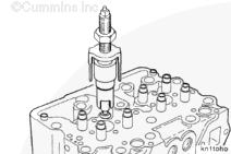
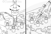
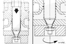
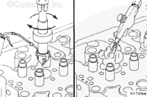
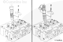
Use injector sleeve puller, Part Number ST-1244, to remove the injector sleeves from the cylinder head.
Install the puller in the injector sleeve with the legs of the bridge against the cylinder head.
When using solvents, acids, or alkaline materials for cleaning, follow the manufacturer’s recommendations for use. Wear goggles and protective clothing to reduce the possibility of personal injury.
WARNING
Wear appropriate eye and face protection when using compressed air. Flying debris and dirt can cause personal injury.
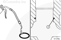
Remove the injector sleeve o-ring from the injector bore in the cylinder head. Discard the o-ring.
Use solvent to clean the injector bore. Dry with compressed air.
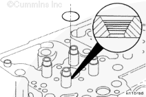
Inspect the grooves (steps) in the bottom of the injector bore.
If the grooves (steps) are damaged, use pilot, Part Number ST-884-6, holder, Part Number ST-884-1, and cutting tool, Part Number ST-788, to machine the grooves (steps) in the bottom of the injector bore.
Install the bead cutting tool and the cylinder head in a drill press. Set the drill press speed at no more than 75 RPM.
Use a cutting oil to lubricate the cutter head.
Carefully machine the bottom of the bore until the grooves (steps) are smooth.
This component or assembly weighs greater than 23 kg [50 lb]. To prevent serious personal injury, be sure to have assistance or use appropriate lifting equipment to lift this component or assembly.
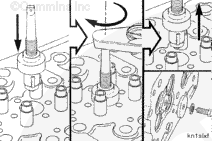
Use vegetable oil to lubricate the injector sleeve o-ring.
Install the o-ring (1) into the groove of the injector sleeve bore.
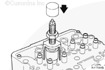
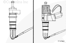
Use an injector sleeve driver, Part Number ST-1227, to push the injector sleeve into the cylinder head. Do not hit the driver with a hammer. Remove the sleeve driver.
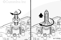
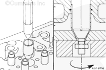
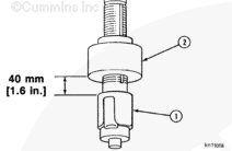
Install an injector sleeve holding tool, Part Number ST-1179, into the injector sleeve and tighten the nut.
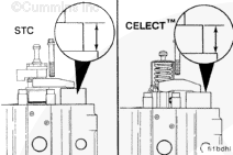
The rollers on the sleeve expander must extend 13.0 to 15.0 mm [0.50 to 0.60 in] below the top of the injector sleeve. Do not extend the rollers more than 15.0 mm [0.60 in] below the top of the sleeve.
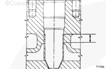
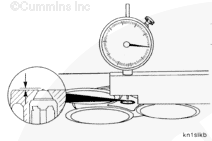
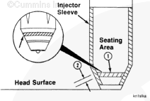
The bluing pattern in the injector seating area (1) must be visible 360 degrees around the seating area.
The injector bore seating width (2) must be a minimum of 1.52 mm [0.060 in].
NOTE: If the injector protrusion is more than the maximum specification, or if the injector sleeve bluing pattern does not meet the specifications given, the injector sleeve must be replaced.
This component or assembly weighs greater than 23 kg [50 lb]. To prevent serious personal injury, be sure to have assistance or use appropriate lifting equipment to lift this component or assembly.
Batteries can emit explosive gases. To reduce the possibility of personal injury, always ventilate the compartment before servicing the batteries. To reduce the possibility of arcing, remove the negative (-) battery cable first and attach the negative (-) battery cable last.
Hello, I'm Jack, a diesel engine fan and a blogger. I write about how to fix and improve diesel engines, from cars to trucks to generators. I also review the newest models and innovations in the diesel market. If you are interested in learning more about diesel engines, check out my blog and leave your feedback.
View all posts by Jack

 WARNING


;)
;)
;)
;)
;)
;)
;)
;)
;)
;)
;)
;)
;)
;)
;)
;)
;)
;)
;)
;)
;)
;)
;)
;)
;)
;)
;)
;)
;)
;)
;)
;)
;)
;)
;)
;)
;)
;)