Wear appropriate eye and face protection when using compressed air. Flying debris and dirt can cause personal injury.
WARNING
When using solvents, acids, or alkaline materials for cleaning, follow the manufacturer’s recommendations for use. Wear goggles and protective clothing to reduce the possibility of personal injury.
WARNING
When using a steam cleaner, wear protective clothing, and safety glasses or a face shield. Hot steam can cause serious personal injury.
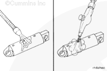
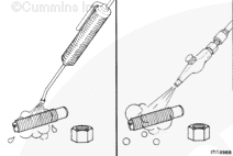
Use steam or solvent to clean the rocker lever shaft. Dry with compressed air.
When using solvents, acids, or alkaline materials for cleaning, follow the manufacturer’s recommendations for use. Wear goggles and protective clothing to reduce the possibility of personal injury.
WARNING
When using a steam cleaner, wear safety glasses or a face shield, as well as protective clothing. Hot steam can cause serious personal injury.
WARNING
Wear appropriate eye and face protection when using compressed air. Flying debris and dirt can cause personal injury.
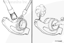
Use steam or solvent to clean the rocker levers, and dry with compressed air.
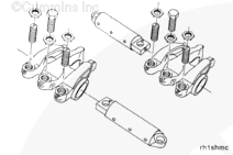
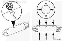
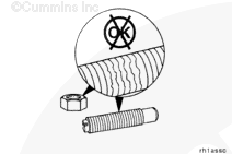
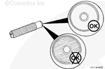
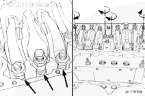
Inspect the adjusting screw. The contact area must be smooth with an even seating pattern.
If parallel scratches are found in the contact area, the adjusting screw must
be replaced. This condition is normally found with worn push rods that will also require replacement.
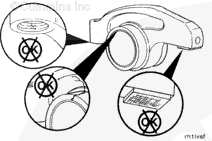
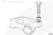
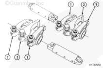
Install the exhaust (1), injector (2), and intake (3) rocker levers onto the shaft.
The two levers closest to the center of the rocker housing are the intake valve rocker levers. The levers closest to the end of the rocker housing are the exhaust valve rocker levers.
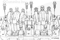
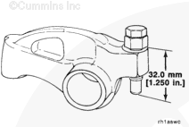
If the adjusting screws protrude beyond the maximum listed below, the push rods can be damaged when the rocker shaft capscrews are tightened. Do not attempt to install the rocker lever shaft assemblies without resetting the lash.
Loosen the rocker lever adjusting screws so there is a maximum of 32 mm [1.250 in] from the top surface of the lever and the ball end of the adjusting screw.
Hello, I'm Jack, a diesel engine fan and a blogger. I write about how to fix and improve diesel engines, from cars to trucks to generators. I also review the newest models and innovations in the diesel market. If you are interested in learning more about diesel engines, check out my blog and leave your feedback.
View all posts by Jack


 CAUTION
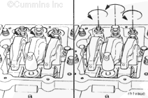
 WARNING


;)
;)
;)
;)
;)
;)
;)
;)
;)
;)
;)
;)
;)
;)
;)
;)
;)
;)
;)
;)
;)
;)
;)
;)
;)
;)
;)
;)
;)
;)
;)
;)