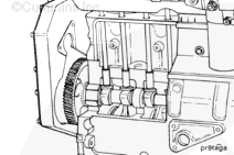
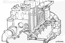
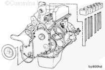
The camshaft is gear-driven from the crankshaft. A replaceable bushing is used for the front journal to carry the side-loading from the accessory drive. The remainder of the journals operate in cast-iron bores in the cylinder block; however, these bores can be repaired in a machine shop by installing service bushings.
Loose rocker levers and the need to reset the valve clearance frequently can indicate camshaft lobe or tappet wear. If an inspection of the levers, valve stems, and push tubes does not show wear, then inspect the tappet or camshaft lobe for wear.
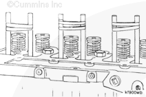
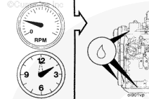
An indication of loose tappets is excessive overhead noise.
Anytime a new camshaft is installed, new tappets and push tubes must be installed to reduce the possibility of damage to the camshaft and tappet surfaces.
The camshaft lobes can be inspected after removing the oil pan. Also, the face of the tappets can be inspected after removing the push tubes and lifting the tappets.
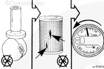
A severely damaged camshaft journal(s) can generate small metal particles that can be found in the oil pan and oil filter. These metal particles will also be indicated as iron in the oil analysis. As the clearance in the journal(s)
increases, a small decrease in oil pressure can be detected.
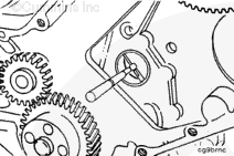
Camshaft Gear Installation/Removal Tool, Part Number 3383589
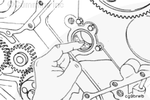
The camshaft end clearance is determined by the clearance between the camshaft and the thrust plate. The camshaft gear must be removed to adjust the camshaft end clearance.
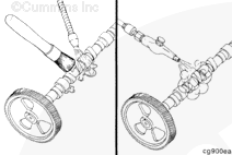
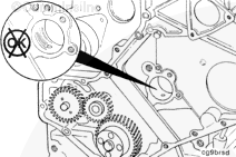
NOTE: The camshaft does not have to be removed to remove the camshaft gear. Use the camshaft installation and removal tool, Part Number 3823589.
Camshafts that are damaged or worn on the valve lobes must
be replaced. Cummins Inc. does not recommend grinding camshaft lobes.
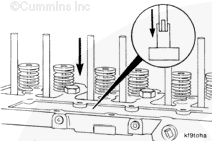
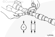
Insert the wooden dowels through the push tube holes and into the top of each tappet securely. When properly installed, the dowels can be used to pull the tappets up and should not be able to be pulled out without considerable effort.
When using a steam cleaner, wear safety glasses or a face shield, as well as protective clothing. Hot steam can cause serious personal injury.
WARNING
When using solvents, acids, or alkaline materials for cleaning, follow the manufacturer’s recommendations for use. Wear goggles and protective clothing to reduce the possibility of personal injury.
WARNING
Wear appropriate eye and face protection when using compressed air. Flying debris and dirt can cause personal injury.
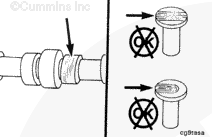
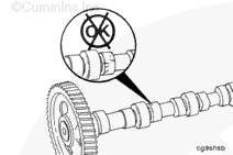
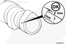
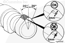
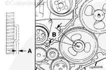
The area of edge deterioration should not be greater than the equivalent area of a 2-mm [0.079-in] circle within ±20 degrees of the nose of the cam lobe.
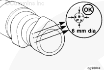
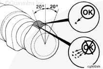
Outside the ±20 degrees of the nose of the cam lobe, the areas of edge deterioration should not be greater than the equivalent area of a 6-mm [0.236-in] circle.
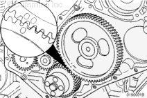
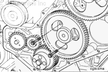
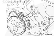
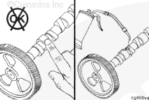
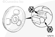
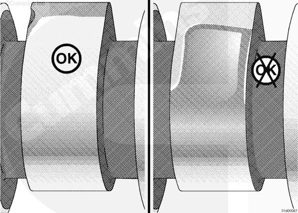
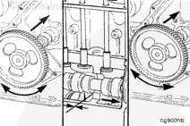
The first of the following illustrations shows normal grain pattern and a casting flaw within the nose area. Both of these conditions are acceptable for reuse.
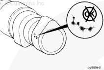
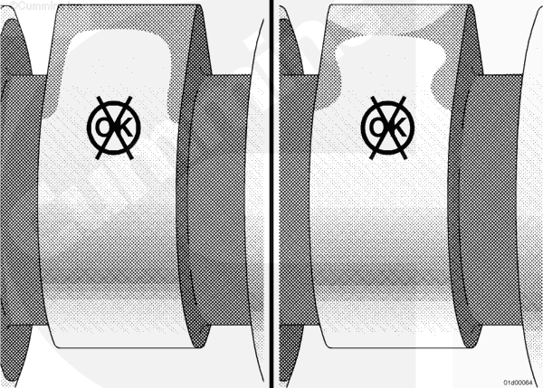
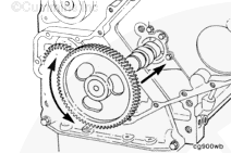
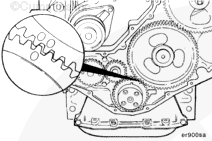
The other three illustrations show wear patterns that are not acceptable for reuse.
NOTE: If the bores without a bushing are worn beyond the limit, the engine must be removed for machining and installation of service bushings or replacement of the cylinder block.
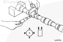
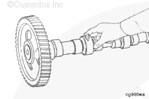
Install the camshaft. While pushing in slightly, rotate the camshaft and carefully work the camshaft through the camshaft bushings. As each camshaft journal passes through a bushing, the camshaft will drop slightly and the camshaft lobes will catch on the bushings. Rotating the camshaft will free the lobe from the bushing and allow the camshaft to be installed.
Do not try to force the camshaft into the camshaft bore or damage to the camshaft bushing can result.
Before the camshaft gear engages the crankshaft gear, check the camshaft for ease of rotation. When installed properly, the camshaft should rotate freely.
Hello, I'm Jack, a diesel engine fan and a blogger. I write about how to fix and improve diesel engines, from cars to trucks to generators. I also review the newest models and innovations in the diesel market. If you are interested in learning more about diesel engines, check out my blog and leave your feedback.
View all posts by Jack

 CAUTION
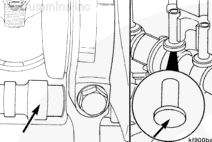


 WARNING


;)
;)
;)
;)
;)
;)
;)
;)
;)
;)
;)
;)
;)
;)
;)
;)
;)
;)
;)
;)
;)
;)
;)
;)
;)
;)
;)
;)
;)
;)
;)
;)
;)
;)
;)
;)
;)
;)
;)
;)
;)
;)
;)
;)
;)
;)
;)
;)
;)
;)
;)
;)
;)
;)
;)
;)
;)
;)
;)
;)
;)
;)
;)
;)
;)
;)
;)
;)
;)
;)