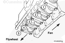
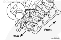
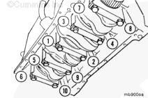
The engine has seven main bearings. The lower bearing shells are all the same. All of the upper bearing shells are also the same with the exception of the journal adjacent to the rear one. The next-to-last journal is fitted with a flanged upper bearing shell and is referred to as thee thrust bearing. The flanges control the end thrust of the crankshaft.
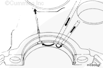
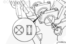
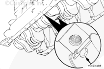
The upper bearings have three holes in them. The middle hole receives lubricating oil from the main oil rifle. One of the adjacent holes is aligned with a drilling in the camshaft journal and serves as an orifice for lubrication flow to the journal. The other adjacent hole supplies lubricating oil for piston cooling. The hole does not align perfectly with the cooling nozzle. The hole is offset to keep it away from the highly loaded bearing area.
Some state and federal agencies have determined that used engine oil can be carcinogenic and cause reproductive toxicity. Avoid inhalation of vapors, ingestion, and prolonged contact with used engine oil. If not reused, dispose of in accordance with local environmental regulations
WARNING
To avoid personal injury, avoid direct contact of hot oil with your skin.
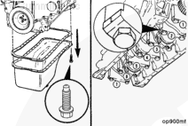
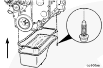
Drain the lubricating oil. Refer to Procedure 007-025.
Remove the lubricating oil pan and gasket. Refer to Procedure 007-025.
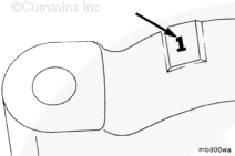
NOTE: Before removing the main bearing caps, make certain that the caps are clearly marked for their location on the lubricating oil cooler side of the main bearing cap.
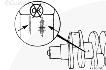
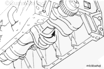
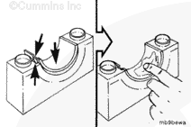
Perform an inspection of the main bearings and crankshaft journals. Remove the number 2 and 3 caps, and check the crankshaft journals for signs of overheating, deep scratches, or other damage. If there is no damage, there is no need to pull the other main bearing caps at this time.
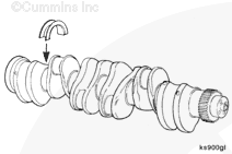
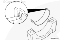
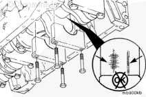
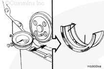
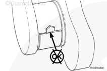
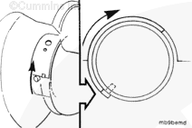
Install the pin into the lubricating oil hole in the crankshaft. Rotate the crankshaft so the pin pushes against the end of the main bearing opposite the tang. Remove the main bearing.
Follow this procedure to remove the other main bearings.
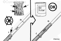
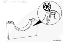
Do not use a scraper or a wire brush. The bearings can be damaged.
WARNING
When using solvents, acids, or alkaline materials for cleaning, follow the manufacturer’s recommendations for use. Wear goggles and protective clothing to reduce the possibility of personal injury.
WARNING
Wear appropriate eye and face protection when using compressed air. Flying debris and dirt can cause personal injury.
NOTE: Make sure the bearings are marked for location. The bearings must be installed in their original location if used again.
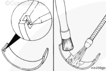
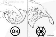
Use solvent and a soft bristle brush to clean bearings.
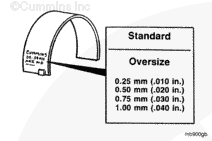
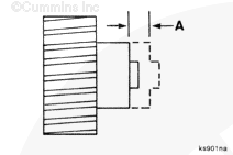
A damaged, worn, or missing thrust bearing flange on the upper main bearing shell can be detected by measuring the end play of the crankshaft. Excessive wear will increase the end play.
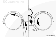
Using the pin, Part Number 3823818, and rotation of the crankshaft, finish pushing the main bearing in slowly, being sure it is aligned with the cylinder block. Make sure the tang on the main bearing sets into the notch.
Use care so the screwdriver does not damage the crankshaft or cylinder block.
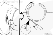
NOTE: The front main, number 1, does not have a hole in the journal, so the pin can not be used to replace the bearing.
Use a flat-blade screwdriver. Gently bump the end of the bearing to loosen it from the cylinder block. Then, use finger pressure against the main bearing shell, and rotate the crankshaft to roll the main bearing out.
Hello, I'm Jack, a diesel engine fan and a blogger. I write about how to fix and improve diesel engines, from cars to trucks to generators. I also review the newest models and innovations in the diesel market. If you are interested in learning more about diesel engines, check out my blog and leave your feedback.
View all posts by Jack
 CAUTION
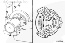
 WARNING


;)
;)
;)
;)
;)
;)
;)
;)
;)
;)
;)
;)
;)
;)
;)
;)
;)
;)
;)
;)
;)
;)
;)
;)
;)
;)
;)
;)
;)
;)
;)
;)
;)
;)
;)
;)
;)
;)
;)
;)
;)
;)
;)
;)
;)
;)
;)
;)
;)
;)
;)
;)
;)
;)
;)
;)
;)
;)
;)
;)
;)
;)