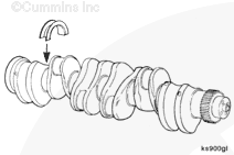
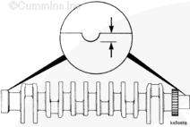
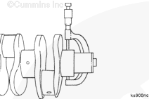
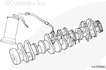
The crankshaft is a balanced, forged-steel unit. The engine has seven main bearings. The lower bearing shells are all the same. All of the upper bearing shells are also the same with the exception of the journal adjacent to the rear one. The next-to-last journal is fitted with a flanged upper bearing shell and is referred to as a thrust bearing. The flanges control the end thrust of the crankshaft.
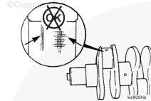
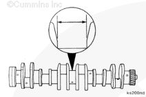
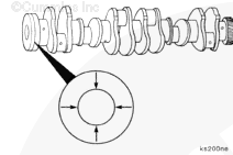
Oversize main bearings and thrust bearings are available for service. Cummins Inc. recommends regrinding all of the main or the connecting rod journals when one requires regrinding. Refer to the B Series Shop Manual, Bulletin 3666017.
Some state and federal agencies have determined that used engine oil can be carcinogenic and cause reproductive toxicity. Avoid inhalation of vapors, ingestion, and prolonged contact with used engine oil. If not reused, dispose of in accordance with local environmental regulations.
WARNING
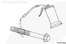
To reduce the possibility of personal injury, avoid direct contact of hot oil with your skin.
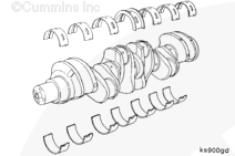
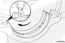
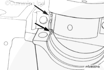
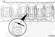
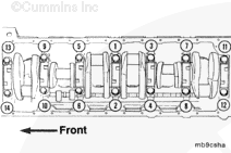
NOTE: The main bearing caps are numbered for location. Number 1 starts with the front of the cylinder block and the numbers must face the camshaft side of the engine.
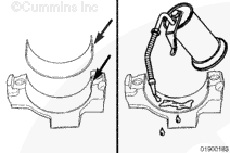
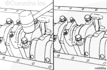
When installed correctly, the main bearing tangs should both be on the same side.
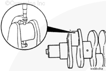
The thrust bearing journal does not have tangs or slots. Care must be taken to make sure the number stamped on the main bearing cap is positioned to the camshaft side of the engine.
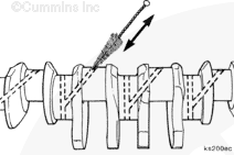
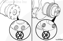
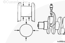
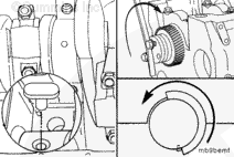
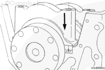
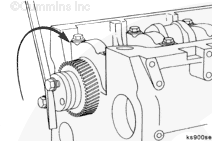
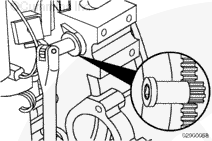
The barring tool inserts into the flywheel housing and engages the flywheel ring gear. The crankshaft can then be rotated by hand using a 1/2-inch-drive ratchet or breaker bar.
Some state and federal agencies have determined that used engine oil can be carcinogenic and cause reproductive toxicity. Avoid inhalation of vapors, ingestion, and prolonged contact with used engine oil. If not reused, dispose of in accordance with local environmental regulations.
WARNING
To reduce the possibility of personal injury, avoid direct contact of hot oil with your skin.
Hello, I'm Jack, a diesel engine fan and a blogger. I write about how to fix and improve diesel engines, from cars to trucks to generators. I also review the newest models and innovations in the diesel market. If you are interested in learning more about diesel engines, check out my blog and leave your feedback.
View all posts by Jack

 WARNING


;)
;)
;)
;)
;)
;)
;)
;)
;)
;)
;)
;)
;)
;)
;)
;)
;)
;)
;)
;)
;)
;)
;)
;)
;)
;)
;)
;)
;)
;)
;)
;)
;)
;)
;)
;)
;)
;)
;)
;)
;)
;)
;)
;)
;)
;)
;)
;)
;)
;)
;)
;)
;)
;)