B5.9G, B5.9LPG – Troubleshooting and Repair Manual – 001-005   Bearings, Connecting Rod

General Information

TOC

In production, steel-backed aluminum connecting rod bearings are used for alternative fuels engines.

 
SMALL | MEDIUM | LARGE


Improper maintenance of the lubrication system is the primary cause of reduced bearing life.

An oil analysis will aid in determining the extent of internal engine damage. Refer to Section 7 for more information.

For additional oil analysis, refer to the Cummins Engine Oil Recommendations, Bulletin 3810340.

SMALL | MEDIUM | LARGE


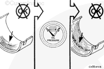
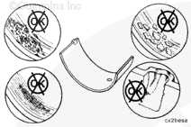
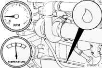
Normally, worn bearings can be detected by reduced oil pressure; but if this wear goes undetected, the excessive clearance will increase the impact between the bearing and crankshaft, causing a distinct knocking sound.

 
SMALL | MEDIUM | LARGE


A connecting rod noise occurs when the engine is not loaded. Check by first applying a load, and then unloading and listening for the noise.

 
SMALL | MEDIUM | LARGE


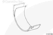
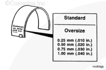
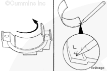
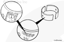
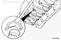
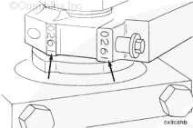
The connecting rod bearing shells are identified by steel-stamped characters on the back of the bearings. The characters indicate either standard (STD)
or the amount of oversize (OS).

 
SMALL | MEDIUM | LARGE
   

Preparatory Steps

TOC

 WARNING 

Some state and federal agencies have determined that used engine oil can be carcinogenic and cause reproductive toxicity. Avoid inhalation of vapors, ingestion, and prolonged contact with used engine oil.
 WARNING 

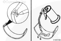
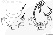
To avoid personal injury, avoid direct contact of hot oil with your skin.

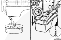
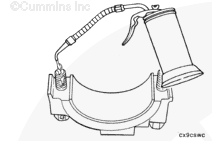
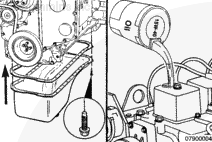
Drain the lubricating oil. Refer to Procedure 007-025.

Remove the lubricating oil pan and gasket and suction tube. Refer to Procedures 007-025 and 007-035.

SMALL | MEDIUM | LARGE
   

Remove

TOC

Engine Barring Tool, Part Number 3824591

Using the barring tool, Part Number 3824591, rotate the crankshaft to the bottom dead center position of the connecting rod.

SMALL | MEDIUM | LARGE


Remove the connecting rod capscrews and connecting rod caps.

SMALL | MEDIUM | LARGE


Remove the lower bearing shell from the connecting rod cap, and mark it with the letter L (lower) and the cylinder number from which it was removed.

SMALL | MEDIUM | LARGE


Push the connecting rod away from the crankshaft to allow the upper bearing shell to be removed.

SMALL | MEDIUM | LARGE


Remove the upper bearing shell, and mark it with the letter U (upper)
and the cylinder number from which it was removed.

SMALL | MEDIUM | LARGE
   

Clean

TOC

 WARNING 

Wear appropriate eye and face protection when using compressed air. Flying debris and dirt can cause personal injury.

Wash the bearing and connecting rod caps.

Dry with compressed air.

SMALL | MEDIUM | LARGE
   

Inspect for Reuse

TOC

Inspect the connecting rod caps, connecting rod bearing saddles, and capscrews for nicks, cracks, burrs, scratches, or frets.

SMALL | MEDIUM | LARGE


Inspect the bearings for damage. Refer to Part Reuse Guidelines, Bulletin 3810303, for more information on bearing inspection.

Replace any bearings that have the following damage:

  • Pits
  • Flakes
  • Corrosion
  • Lock tang damage
  • Scratches
  • Heavy wear.

SMALL | MEDIUM | LARGE


Inspect the bearing shell seating surface for nicks or burrs.

If nicks or burrs can not be removed with Scotch-Brite™ 7448 or equivalent, the bearings must be replaced.

NOTE: If bearings are damaged, they must be replaced as a set.

SMALL | MEDIUM | LARGE


Use an outside diameter ball-tipped micrometer to measure the connecting rod bearing thickness.

Connecting Rod Bearing Thickness
mm in
Standard 1.955 MIN 0.0770
  1.968 MAX 0.0775
0.25 mm Oversize 2.080 MIN 0.0819
  2.093 MAX 0.0824
0.50 mm Oversize 2.205 MIN 0.0868
  2.218 MAX 0.0873
0.75 mm Oversize 2.330 MIN 0.0917
  2.343 MAX 0.0922
1.00 mm Oversize 2.455 MIN 0.0967
  2.468 MAX 0.0972

SMALL | MEDIUM | LARGE


NOTE: Connecting rod bearings are identified with the part number and size stamped on the back.

Determine the size of the removed rod bearing, and obtain a set of the same size.

NOTE: Oversize service rod bearings are available for use with crankshafts that have been machined undersize.

SMALL | MEDIUM | LARGE


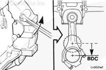
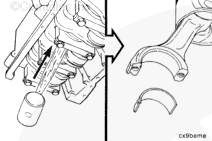
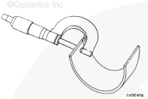
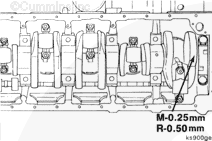
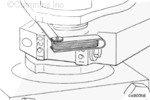
Crankshafts that are machined undersize on the connecting rod or main bearing journals are marked on the front counterweight. If the crankshaft is marked, check the bearing shell part number to make sure the correct bearing size is used.

NOTE: Bearing shells are identified by steel-stamped characters on the back of the bearings to indicate either standard (STD) or oversize (OS).

SMALL | MEDIUM | LARGE
   

Install

TOC

NOTE: Used bearings must be installed in the same location from which they were removed.

Use clean lubricating engine oil to coat the inside diameter of the bearing shell.

SMALL | MEDIUM | LARGE


Install the upper bearing shell in the connecting rod with the tang of the bearing in the slot of the connecting rod.

SMALL | MEDIUM | LARGE


Install the bearing shell in the connecting rod cap with the tang of the bearing in the slot of the connecting rod cap.

Use clean lubricating engine oil to coat the inside diameter of the bearing shell.

SMALL | MEDIUM | LARGE


Use clean lubricating engine oil to lubricate the threads and underside of the connecting rod capscrew head.

SMALL | MEDIUM | LARGE


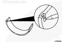
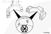
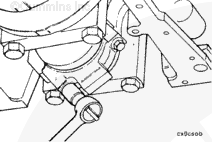
The four-digit number stamped on the connecting rod and connecting rod cap at the parting line must match and be installed on the lubricating oil cooler side of the engine.

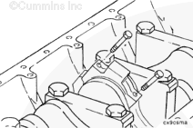
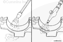
Install the connecting rod cap and capscrews to the connecting rod.

SMALL | MEDIUM | LARGE


Torque Wrench

Alternately tighten the two capscrews.

Torque Value: Step 1 30 n.m   [22 ft-lb]
  Step 2 60 n.m   [44 ft-lb]
  Step 3 Turn clockwise 60 degrees.

SMALL | MEDIUM | LARGE


Measure the side clearance between the connecting rod and crankshaft using feeler gauges.

Do not measure the clearance between the connecting rod cap and crankshaft.

Connecting Rod Side Clearance Limits
mm in
0.10 MIN 0.004
0.33 MAX 0.013

SMALL | MEDIUM | LARGE


NOTE: The crankshaft must rotate freely.

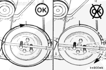
Check for freedom of rotation as the connecting rod caps are installed. If the crankshaft does not rotate freely, check the installation of the connecting rod bearings and bearing size.

SMALL | MEDIUM | LARGE


Install the suction tube, lubricating oil pan, and gasket. Refer to Procedures 007-025 and 007-035.

Lubricating Oil Pan 24 n.m [212 in-lb]

Lubricating Suction Tube 24 n.m [212 in-lb]

NOTE: Capacity including filters is 15.1 liters [16.0 qt.].

Fill the engine with clean gas engine lubricating oil.

SMALL | MEDIUM | LARGE


Operate the engine to normal operating temperature, and check for leaks.

SMALL | MEDIUM | LARGE
Last Modified:  27-Jun-2002