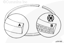
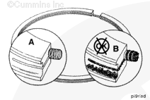
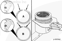
NOTE: Abrasive wear is indicated by concentrated vertical scratches (B). The chromium plate is worn through and the face of the ring has a brighter finish compared to the dull satin finish of a new ring (A).
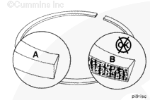
NOTE: Scuffing and scoring are indicated by heavy scratches, metal discoloration, and voids (B).
Scuffing and scoring can be caused by:
Engine overheating
Oil dilution
Improper maintenance of the lubrication system
Piston cooling nozzle malfunction
Oil ring plugged by deposits.
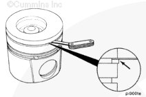
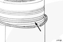
NOTE: Scuffing and scoring on the piston rings indicate a breakdown of the oil film on the cylinder liner wall, causing transfer of material from the piston ring face to the cylinder liner.
Hello, I'm Jack, a diesel engine fan and a blogger. I write about how to fix and improve diesel engines, from cars to trucks to generators. I also review the newest models and innovations in the diesel market. If you are interested in learning more about diesel engines, check out my blog and leave your feedback.
View all posts by Jack


 CAUTION
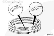

;)
;)
;)
;)
;)
;)
;)
;)
;)
;)
;)
;)
;)
;)
;)
;)
;)
;)
;)
;)
;)
;)
;)
;)
;)
;)
;)
;)
;)
;)