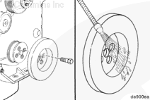
The vibration damper controls the torsional vibration of the crankshaft. A vibration damper is engineered for use on a specific engine model.
It is not economical to repair a vibration damper in the field. Install a new or rebuilt vibration damper if the inspection indicates that a damper is defective.
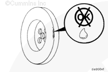
The viscous vibration damper has a limited service life. The damper must be replaced if worn or damaged.
When using solvents, acids, or alkaline materials for cleaning, follow the manufacturer’s recommendations for use. Wear goggles and protective clothing to reduce the possibility of personal injury.
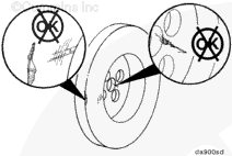
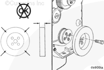
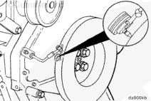
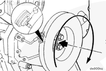
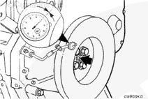
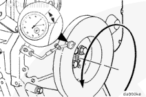
The viscous damper is filled with a silicone fluid. After many hours of use, the silicone fluid can become thicker and expand. To determine if the damper thickness is correct, remove the paint from the damper in four locations on either side of the damper. Measure and record the thickness of the damper in four places. Measure the thickness 3.18 mm [0.125 in] from the outside of the damper. Replace the damper if its thickness varies by more than 0.25 mm [0.010 in].
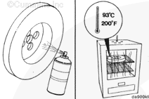
Spray the damper with spot check developer, type SKD-NF, or its equivalent. Heat the damper in an oven (rolled-lip side down) at 93°C [199°F] for 2 hours.
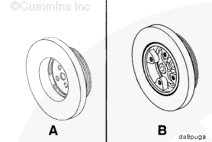
NOTE: The B Series engines have two configurations for the crankshaft pulleys and vibration dampers. Determine which configuration is used and use the appropriate steps in this procedure.
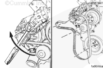
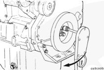
Install the drive belt. Refer to Procedure 008-002.
Service Tip: If difficulty is experienced installing the drive belt (the belt seems too short), position the belt over the grooved
pulleys first, and then, while holding the tensioner up, slide the belt over
the water pump pulley.
Hello, I'm Jack, a diesel engine fan and a blogger. I write about how to fix and improve diesel engines, from cars to trucks to generators. I also review the newest models and innovations in the diesel market. If you are interested in learning more about diesel engines, check out my blog and leave your feedback.
View all posts by Jack


 WARNING


;)
;)
;)
;)
;)
;)
;)
;)
;)
;)
;)
;)
;)
;)
;)
;)
;)
;)
;)
;)
;)
;)
;)
;)
;)
;)
;)
;)