B5.9G, B5.9LPG – Troubleshooting and Repair Manual – 001-054   Piston and Connecting Rod Assembly

General Information

TOC

There are a number of power-related problems, including excessive lubricating oil consumption, smoke, blowby, and poor performance, that can be caused by inadequate sealing between the piston rings and the cylinder walls. A blowby measurement can help detect the problem. Refer to Procedure 014-002.

SMALL | MEDIUM | LARGE


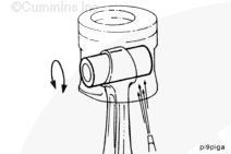
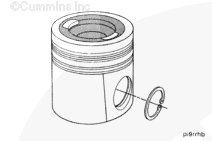
A free-floating, hollow piston pin is used to attach the piston to the connecting rod. Lubricating the pin and journal is accomplished by residual spray from piston cooling.

 
SMALL | MEDIUM | LARGE


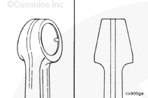
The piston pin end of the connecting rod is angle-cut to provide additional bearing surface. The connecting rod end is fitted with a bronze bushing.

 
SMALL | MEDIUM | LARGE
   

Remove

TOC

 WARNING 

To reduce the possibility of personal injury, avoid direct contact of hot oil with your skin.

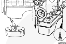
Drain the lubricating oil. Refer to Procedure 007-025.

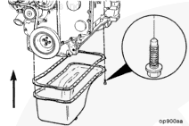
Remove the lubricating oil pan and gasket. Refer to Procedure 007-025.

SMALL | MEDIUM | LARGE


 WARNING 

Coolant is toxic. Keep away from children and pets. If not reused, dispose of in accordance with local environmental regulations.

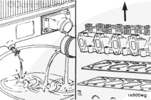
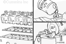
Drain the coolant. Refer to Procedure 008-018.

Remove the cylinder head. Refer to Procedure 002-004.

SMALL | MEDIUM | LARGE


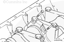
Mark each connecting rod cap according to cylinder.

 
SMALL | MEDIUM | LARGE


Engine Barring Tool, Part Number 3824591

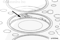
Rotate the crankshaft with engine barring tool, Part Number 3824591, until the pistons are below the carbon deposits, which are found above the ring travel area.

SMALL | MEDIUM | LARGE


 CAUTION 
Do not use sandpaper or an emery cloth to remove carbon from the cylinder bores. Aluminum oxide or silicon particles from these materials can cause serious engine damage.

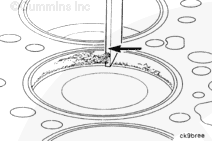
Use a scraper or a blunt-edged instrument to loosen the carbon deposits. Do not damage the cylinder with the scraper.

SMALL | MEDIUM | LARGE


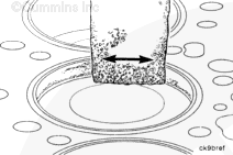
NOTE: When cleaning the cylinder bore, perform a cylindrical motion, not a vertical one, to make sure no leak paths are made.

Remove the remaining carbon with a Scotch-Brite cleaning pad, or equivalent.

SMALL | MEDIUM | LARGE


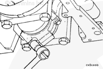
Remove the capscrews, connecting rod cap, and connecting rod bearings. Refer to Procedure 001-005.

SMALL | MEDIUM | LARGE


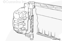
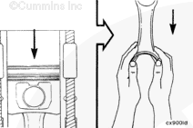
Push the connecting rod and piston assembly out of cylinder bore. Care
must be taken not to mutilate the connecting rod or bearing.

SMALL | MEDIUM | LARGE


Use both hands to remove the piston and rod assembly.

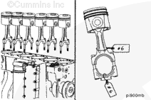
NOTE: The piston and connecting rod assemblies must be installed in the same cylinder from which they were removed. This will allow for the proper fit of worn mating surfaces, if the parts are used again.

Use a tag to mark the cylinder number from which each piston and rod assembly was removed.

SMALL | MEDIUM | LARGE


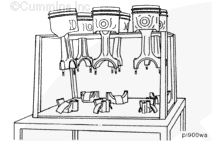
Place the connecting rod and piston assemblies in a container to protect them from damage.

 
SMALL | MEDIUM | LARGE
   

Disassemble

TOC

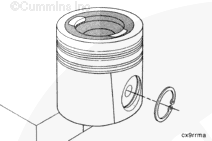
Remove the retaining rings.

Refer to Procedure 001-047.

SMALL | MEDIUM | LARGE


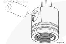
Remove the piston pin.

Refer to Procedure 001-043.

NOTE: Heating the piston is not required.

SMALL | MEDIUM | LARGE


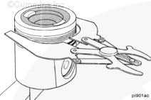
Piston Ring Expander, Part Number 3823137

Remove the piston rings.

NOTE: Refer to Procedure 001-043 for cleaning and inspection of pistons.

SMALL | MEDIUM | LARGE
   

Assemble

TOC

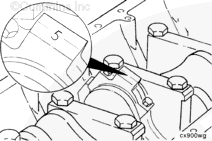
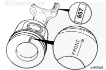
Be sure FRONT marking on piston and the numbers on the connecting rod and cap are oriented as illustrated.

 
SMALL | MEDIUM | LARGE


Install the retaining ring in the pin groove on the frontside of the piston.

SMALL | MEDIUM | LARGE


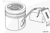
Lubricate the pin and pin bores with clean gas engine lubricating oil.

SMALL | MEDIUM | LARGE


Install the pin. Refer to Procedure 001-043.

NOTE: Pistons do not require heating to install the pin; however, the pistons do need to be at room temperature or above.

SMALL | MEDIUM | LARGE


Install the second retaining ring.

SMALL | MEDIUM | LARGE
   

Install

TOC

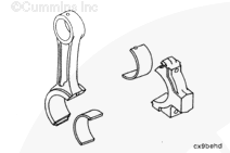
Install the bearing shells into both the connecting rod and the connecting rod cap. Make sure the tang on the bearing shells is in the slot of the connecting rod cap and connecting rod.

SMALL | MEDIUM | LARGE


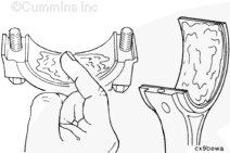
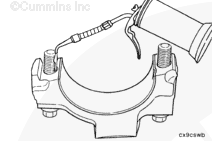
Lubricate the connecting rod bearings with a light film of clean lubricating engine oil.

SMALL | MEDIUM | LARGE


Install the piston rings. Refer to Procedure 001-047.

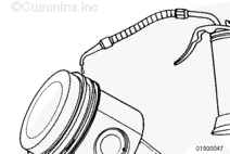
Lubricate the rings and piston skirts with clean gas engine lubricating oil.

SMALL | MEDIUM | LARGE


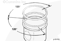
Position the rings so that the ring gaps are 120 degrees apart.

SMALL | MEDIUM | LARGE


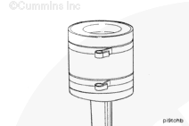
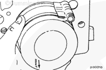
Piston Ring Compressor, Part Number 3823290

75 to 125 mm [3 to 5 in]

 CAUTION 
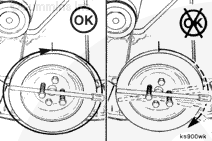
If using a strap-type ring compressor, make sure the inside end of the strap does not hook on a ring gap and break the ring.

Compress the rings.

SMALL | MEDIUM | LARGE


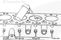
Lubricate the cylinder bore with clean gas engine lubricating oil.

SMALL | MEDIUM | LARGE


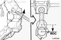
Engine Barring Tool, Part Number 3824591

Position the connecting rod journal for the piston to be installed to bottom dead center.

SMALL | MEDIUM | LARGE


Take care not to damage the cylinder wall when inserting the connecting rod.

Position the piston and connecting rod assembly into cylinder bore with the word FRONT on the piston toward the front of the cylinder block.

SMALL | MEDIUM | LARGE


Carefully push the piston into the bore while guiding the connecting rod to the crankshaft journal.

SMALL | MEDIUM | LARGE


Lubricate the threads and underside of the connecting rod capscrew heads with clean lubricating engine oil.

SMALL | MEDIUM | LARGE


NOTE: The number stamped on the rod and cap at the parting line must match and be installed on the oil cooler side of the engine.

Install the connecting rod cap and capscrews to the connecting rod.

SMALL | MEDIUM | LARGE


Alternately, tighten the two capscrews.

Torque Value: Step 1 30 n.m   [22 ft-lb]
  Step 2 60 n.m   [44 ft-lb]
  Step 3 Turn 60 degrees clockwise.

SMALL | MEDIUM | LARGE


NOTE: Do not measure the clearance between the rod cap and crankshaft.

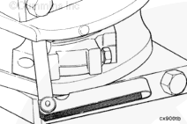
Measure the side clearance between the connecting rod and crankshaft using a feeler gauge.

Side Clearance Limits
mm in
0.10 MIN 0.004
0.33 MAX 0.013

SMALL | MEDIUM | LARGE


 CAUTION 
The crankshaft must rotate freely. If the connecting rod is not properly oriented (tang opposite the camshaft), it will contact the camshaft and lock the engine.

Check for freedom of rotation as the connecting rod caps are installed. If the crankshaft does not rotate freely, check the installation of the connecting rod bearings and the bearing size.

SMALL | MEDIUM | LARGE


Three-Bond™ Sealant, Part Number 3823494

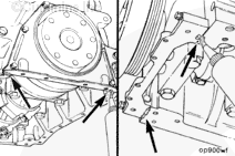
Oil Pan Sealing Surfaces – Sealants

Use Cummins sealant, Part Number 3823494, to fill the joints between the lubricating oil pan rail, gear housing, and rear cover.

SMALL | MEDIUM | LARGE


Install the lubricating oil pan and gasket. Refer to Procedure 007-025.

Refer to Section 7 for correct oil specifications.

Torque Value:  24  n.m  [212 in-lb]

SMALL | MEDIUM | LARGE


Install the cylinder head. Refer to Procedure 002-004.

Fill the cooling system. Refer to Procedure 008-018.

Fill the engine with clean gas engine lubricating oil. Refer to Procedure
007-025.

SMALL | MEDIUM | LARGE


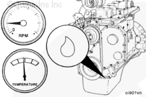
Operate the engine to normal operating temperature, and check for leaks.

SMALL | MEDIUM | LARGE
Last Modified:  27-Jun-2002