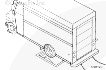
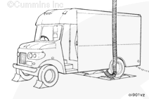
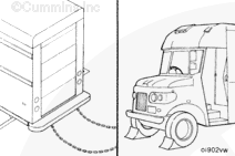
The performance of an engine installed in on-highway vehicles can be tested on a chassis dynamometer.
NOTE: Due to driveline efficiency and engine-driven accessories, the engine horsepower when measured at the rear wheels will be reduced by approximately:
20 percent for single-axle vehicles
25 percent for tandem-axle vehicles.
NOTE: These percentages are used for engine run-in only and are not to be used as absolute figures.
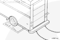
Follow all the vehicle manufacturer’s safety precautions before installing or operating a vehicle on a chassis dynamometer. Failure to do so can result in personal injury or death.
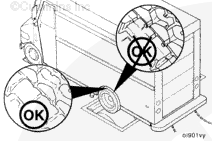
Low-profile radial tires are more sensitive to heat than bias-ply tires. Excessive operating time at full load can damage tires due to overheating. Check the tire manufacturer’s recommendations for the maximum allowable chassis dynamometer operating time.
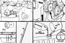
The following procedure assumes that the lubricating oil and fuel supply systems are correct, the dipstick calibrated, and the engine filled to the correct levels with lubricating oil and coolant during installation of the engine into the chassis. If these systems were not serviced during installation of the engine, refer to Procedure 014-006 (Engine Run-In (Engine Dynamometer) in Section 14 for instructions on priming the lubricating oil and the fuel system requirements, and calibrating the dipstick. Refer to the Operation and Maintenance Manual, B5.9G, Bulletin 3666112, or Operation and Maintenance Manual, B5.9LPG, Bulletin 3666213, for instructions on filling the lubricating oil and the cooling systems.
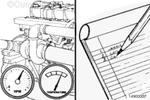
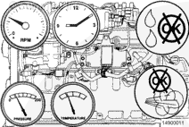
The number of instruments and gauges required to perform a chassis dynamometer test will vary according to the type and the capability of the test equipment used.
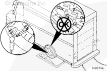
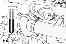
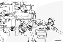
Connect a water manometer, Part Number ST-1111-3, to the turbocharger air inlet pipe to test air restriction.
NOTE: The manometer connection must be installed at a 90-degree angle to the airflow in a straight section of pipe, one pipe diameter before the turbocharger.
NOTE: A vacuum gauge, Part Number ST-434, can be used in place of the water manometer.
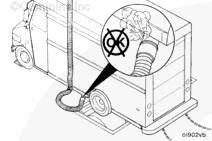
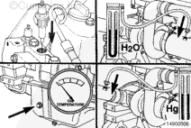
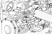
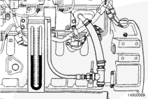
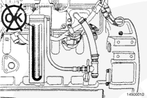
Measure the blowby by installing blowby checking tool, Part Number 3822476, in the crankcase breather vent. Connect the blowby tool to a water manometer.
NOTE: Excessive blowby indicates a turbocharger malfunction or an internal engine component malfunction, allowing combustion gases to enter the crankcase.
NOTE: If a sudden increase in blowby occurs or if blowby exceeds the maximum allowable limit during any run-in step, return to the previous step and continue the run-in. If blowby does not reach an acceptable level, discontinue the run-in and determine the cause.
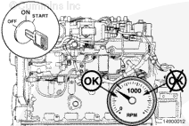
NOTE: Avoid long idle periods. Operate the engine at low idle only long enough (3 to 5 minutes) to check for correct lubricating oil pressure and any gas, lubricating oil, water, or air leaks.
Do not operate the engine at idle speed longer than specified during engine run-in. Excessive carbon formation can cause damage to the engine.
CAUTION
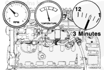
Do not shut off the engine immediately after the last step of the run-in is completed. Allow the engine to cool by operating at low idle for a minimum of 3 minutes to avoid internal component damage.
Hello, I'm Jack, a diesel engine fan and a blogger. I write about how to fix and improve diesel engines, from cars to trucks to generators. I also review the newest models and innovations in the diesel market. If you are interested in learning more about diesel engines, check out my blog and leave your feedback.
View all posts by Jack
 WARNING
 CAUTION
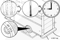


;)
;)
;)
;)
;)
;)
;)
;)
;)
;)
;)
;)
;)
;)
;)
;)
;)
;)
;)
;)
;)
;)
;)
;)
;)
;)
;)
;)
;)
;)
;)
;)
;)
;)
;)
;)
;)
;)