Excessive crankcase blowby can indicate an engine or engine related component malfunction that allows combustion gasses or air to enter the crankcase. This results in the buildup of higher than normal crankcase pressure, which results in increased levels of blowby.
This procedure describes how to measure crankcase blowby and how to determine what component is malfunctioning.
Blowby is typically measured for the following situations:
Verifying engine break-in after an engine rebuild
Troubleshooting for excessive lubricating oil out of the crankcase breather tube, commonly referred to as oil carryover (for open crankcase ventilation systems)
Troubleshooting oil in the air intake system (for closed crankcase ventilation systems)
Troubleshooting high crankcase pressure (for engines equipped with a crankcase pressure sensor)
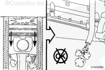
Troubleshooting possible internal engine damage (worn piston rings, valve stem seals or guides, turbocharger, air compressor, etc.).
NOTE: For specific crankcase gases (blowby) symptom information and direction, use Troubleshooting Symptom Tree t027 (Crankcase Gases (Blowby) Excessive) in the appropriate engine service manual.
The following measure step will give general guidelines for measuring blowby relative to the above situations.
NOTE: Some illustrations in this procedure do not show actual engine configurations, however, the procedure is the same.
It is important to note that commonly the terms blowby and carryover (oil out of the breather tube) are used interchangeably.
When measuring blowby and there is an excessive amount of oil coming out of the breather tube, the quantity of oil can affect the blowby measurement.
The blowby measurement is affected by the oil collecting on the orifice of the blowby measurement service tool. This reduces the size of the orifice, which results in higher than actual blowby measurements.
If this occurs it will be necessary to:
Find a different location on the engine to measure blowby (oil fill, oil fill cap, unused turbocharger drain location, etc.)
Clean any oil residue from the breather and dry thoroughly before measuring blowby
Determine if there is an issue causing the breather to be flooded with oil, for example
Incorrect oil level
Vehicle operation (excessive angularity, excessive engine side to side movement)
Internal engine components are deflecting oil toward the breather cavity (piston cooling nozzles, accessory oil drains, etc.)
Determine if another breather option is available for the engine being serviced.
The tools used to measure blowby are similar in design. The difference between the tools is in the size of the orifice. Different size orifices are available to more accurately measure blowby and to accommodate the wide variety of engine configurations and ratings. This is due to the fact that engine blowby is dependent on the volume of intake airflow.
For example:
If measuring blowby on two identically configured and size engines, but the horsepower ratings and rated speed are different, the maximum blowby values measured will be different.
The engine with the higher horsepower rating and rated speed will have a higher volume of intake airflow, which will result in higher blowby. This means that if the smaller orifice blowby tool was used on the engine with a higher horsepower rating and rated speed, the measurement can exceed the limits of the pressure measuring tool.
Blowby Tool Part Number
Orifice Size mm [in]
3822476
5.61 mm [0.221 in]
3822566
7.67 mm [0.302 in]
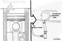
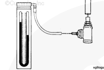
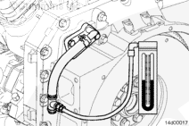
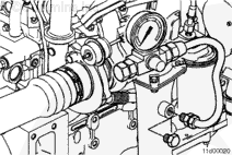
To measure the crankcase blowby pressure, connect a water manometer, Part Number ST1111-3, or equivalent, pressure gauge or transducer to the blowby tool.
NOTE: Water manometer, Part Number ST1111-3, can measure a maximum of 944 mm [36 in] of water.
The following charts show the relationship of measured pressure to flow rate depending on the blowby tool used.
Blowby Conversion Table (5.61-mm [0.221-in] orifice, Blowby Tool, Part Number 3822476)
mm [in] of H2O
Liter [cfm] per Minute
25.4 [1]
27 [0.953]
50.8 [2]
40 [1.413]
76.2 [3]
48 [1.695]
101.6 [4]
58 [2.048]
127 [5]
64 [2.260]
152.4 [6]
71 [2.507]
177.8 [7]
76 [2.684]
203.2 [8]
81 [2.860]
228.6 [9]
86 [3.037]
254 [10]
90 [3.178]
279.4 [11]
94 [3.320]
304.8 [12]
98 [3.461]
330.2 [13]
102 [3.602]
355.6 [14]
105 [3.708]
381 [15]
109 [3.849]
406.4 [16]
112 [3.955]
431.8 [17]
115 [4.061]
457.2 [18]
118 [4.167]
482.6 [19]
121 [4.723]
508 [20]
124 [4.379]
533.4 [21]
128 [4.520]
558.2 [22]
131 [4.626]
584.2 [23]
135 [4.767]
609.6 [24]
137 [4.838]
635 [25]
140 [4.944]
660.4 [26]
144 [5.085]
685.8 [27]
147 [5.191]
711.2 [28]
150 [5.297]
736.6 [29]
154 [5.438]
762 [30]
157 [5.544]
787.4 [31]
160 [5.650]
812.8 [32]
163 [5.756]
838.2 [33]
166 [5.862]
863.6 [34]
169 [5.968]
889 [35]
172 [6.074]
Blowby Conversion Table (7.67-mm [0.302-in] orifice, Blowby Tool, Part Number 3822566)
mm [in] of H2O
Liter [cfm] per Minute
25.4 [1]
50 [1.766]
50.8 [2]
84 [2.966]
76.2 [3]
103 [3.637]
101.6 [4]
119 [4.202]
127 [5]
133 [4.697]
152.4 [6]
145 [5.121]
177.8 [7]
155 [5.474]
203.2 [8]
164 [5.792]
228.6 [9]
172 [6.074]
254 [10]
180 [6.357]
279.4 [11]
187 [6.604]
304.8 [12]
193 [6.816]
330.2 [13]
200 [7.063]
355.6 [14]
206 [7.275]
381 [15]
211 [7.451]
406.4 [16]
217 [7.663]
431.8 [17]
222 [7.840]
457.2 [18]
226 [7.981]
482.6 [19]
229 [8.087]
508 [20]
235 [8.299]
533.4 [21]
239 [8.440]
558.8 [22]
242 [8.546]
584.2 [23]
246 [8.687]
609.6 [24]
248 [8.758]
The following chart contains general blowby specifications for MidRange engines. Due to the wide variety of engine types, configurations, and ratings, these specifications are intended to only be used as a guide to help identify if a problem exists. These specifications are not intended to be used as engine condemning limits.
NOTE: If internal engine damage is suspected to be the cause of the excessive blowby condition, other steps can be taken to confirm this.
Measuring blowby must only be considered when confirming engine break-in after a rebuild or if another symptom is present. These symptoms can include:
Excessive carryover (oil out of the crankcase breather tube)
High crankcase pressure (for engines equipped with a crankcase pressure sensor)
Low power
Oil consumption
Exhaust smoke.
If no other symptom is present, blowby measurements need not be taken.
NOTE: The location and type of crankcase breathers vary by engine configuration (Front Gear Train or Rear Gear Train) and/or engine application (Marine, Industrial, and Automotive).
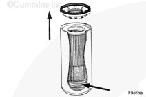
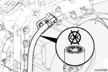
Prior to measuring blowby pressure, check the crankcase breather tube for obstructions.
Reference the following procedure in the ISB and QSB5.9-44 Engines Troubleshooting and Repair Manual, Bulletin 3666193. Refer to Procedure 003-018 in Section 3.
Reference the following procedure in the ISBe, ISB, and QSB (Common Rail Fuel System) Service Manual, Bulletin 4021271. Refer to Procedure 003-018 in Section 3.
Reference the following procedure in the Industrial QSB3.9-30, QSB4.5-30, and QSB5.9-30 Series Engines Troubleshooting and Repair Manual, Bulletin 4021398. Refer to Procedure 003-018 in Section 3.
Reference the following procedure in the ISC, ISCe, QSC8.3, ISL, ISLe3, ISLe4 and QSL9 Engines Troubleshooting and Repair Manual, Bulletin 4021418. Refer to Procedure 003-018 in Section 3.
Reference the following procedure in the B4.5s and B6.7s Series Engines Troubleshooting and Repair Manual, Bulletin 4095243. Refer to Procedure 003-018 in Section 3.
If troubleshooting a complaint of excessive oil out of the breather tube, it can be necessary to remove the breather components to clean and remove any lubricating oil buildup before performing any blowby measurements.
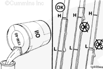
Check the engine oil level and, if necessary, proper calibration of the dipstick. If the level is too high, it can cause a higher than normal blowby pressure and/or excessive carryover.
Reference the following procedure in the ISB and QSB5.9-44 Engines Troubleshooting and Repair Manual, Bulletin 3666193. Refer to Procedure 007-011 in Section 7.
Reference the following procedure in the ISBe, ISB, and QSB (Common Rail Fuel System) Service Manual, Bulletin 4021271. Refer to Procedure 007-011 in Section 7.
Reference the following procedure in the Industrial QSB3.9-30, QSB4.5-30, and QSB5.9-30 Series Engines Troubleshooting and Repair Manual, Bulletin 4021398. Refer to Procedure 007-011 in Section 7.
Reference the following procedure in the ISC, ISCe, QSC8.3, ISL, ISLe3, ISLe4 and QSL9 Engines Troubleshooting and Repair Manual, Bulletin 4021418. Refer to Procedure 007-011 in Section 7.
Choose the appropriate blowby measurement service tool to use for the engine being serviced. Reference the MidRange Blowby Specifications Chart in this procedure and determine the appropriate blowby measurement service tool to use, based on engine type and/or horsepower.
Blowby Tool Part Number
Orifice Size mm [in]
3822476
5.61 mm [0.221 in]
3822566
7.67 mm [0.302 in]
NOTE: Either service tool can be used to measure blowby as long as the blowby measurement is correctly matched to the correct flow rate. Reference the flow rate conversion tables in this procedure for the correct orifice.
To measure the crankcase blowby pressure, connect a water manometer, Part Number ST1111-3, pressure gauge, or transducer to the blowby measurement service tool.
NOTE: The location of the crankcase breather tube can vary by engine configuration (front gear train or rear gear train) and/or application (Marine, Industrial, and Automotive). See Section E (Engine Identification) for crankcase breather tube locations.
Install the appropriate blowby service tool(s):
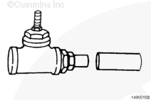
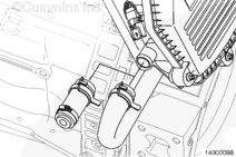
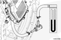
For typical open crankcase breather/ventilation systems, connect the appropriate blowby service tool to the end of the crankcase breather tube. Connect a water manometer pressure gauge or transducer to the blowby service tool.
For engines with closed crankcase ventilation systems (without a crankcase ventilation filter), disconnect the breather tube and plug the intake manifold or turbocharger compressor housing port. Connect the appropriate blowby service tool to the end of the crankcase breather tube. Connect a water manometer pressure gauge or transducer to the blowby service tool.
For crankcase breather/ventilation systems with crankcase ventilation filters, follow the proceeding steps on connecting the blowby measurement equipment.
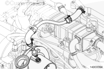
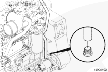
For ISB CM2150 engines that have the crankcase ventilation filter located on top of the rocker lever cover, use the following steps to connect the blowby measurement tools.
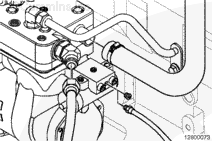
Disconnect the crankcase ventilation line from the turbocharger/OEM intake plumbing. If the crankcase ventilation line is connected to the turbocharger housing, remove the inlet fitting.
If the crankcase ventilation line is connected to the turbocharger housing, install a straight thread plug, Part Number 3089567. Plug the crankcase ventilation line with a suitable fitting.
NOTE: If the crankcase ventilation line is connected to the OEM intake plumbing (not shown), use a suitable fitting to plug the port in the intake plumbing. Also plug the crankcase ventilation line coming from the engine with a suitable fitting.
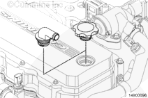
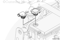
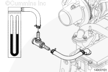
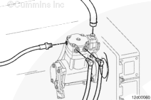
Connect the appropriate blowby service tool to the outlet of the oil fill adapter. Connect a water manometer, pressure gauge, or transducer to the blowby service tool.
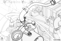
For ISB CM2150 engines that have the crankcase ventilation filter located at the rear of the engine, use the following steps to connect the blowby measurement tools.
Disconnect the crankcase ventilation line from the crankcase ventilation filter housing. Plug or cap the crankcase ventilation filter housing.
Connect the appropriate blowby service tool to the crankcase ventilation line exiting the flywheel housing. Connect a water manometer, pressure gauge, or transducer to the blowby service tool.
Connect the appropriate blowby service tool to the outlet of the oil fill adapter. Connect a water manometer, pressure gauge, or transducer to the blowby service tool.
When measuring blowby and there is an excessive amount of oil coming out of the breather tube, the quantity of oil can affect the blowby measurement.
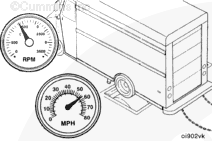
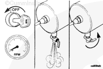
Operate the engine at rated rpm and full load until a steady reading is obtained.
NOTE: When measuring blowby, the value can “spike” initially as the engine reaches peak power and rated speed. Wait for the blowby measurement to stabilize before taking a reading.
NOTE: For engine run-in, if a sudden increase in blowby occurs, or if blowby exceeds the maximum allowable limit during any run-in step, return to the previous step and continue the run-in. If blowby does not reach an acceptable level, discontinue the run-in and determine the cause.
Record the steady blowby measurement.
Remove the engine blowby service tool and water manometer or pressure gauge if the blowby is within specification.
Reference the following procedure in the Industrial QSB3.9-30, QSB4.5-30, and QSB5.9-30 Series Engines Troubleshooting and Repair Manual, Bulletin 4021398. Refer to Procedure 010-045 in Section 10.
Reference the following procedure in the ISC, ISCe, QSC8.3, ISL, ISLe3, ISLe4 and QSL9 Engines Troubleshooting and Repair Manual, Bulletin 4021418. Refer to Procedure 010-045 in Section 10.
Reference the following procedure in the B4.5s and B6.7s Series Engines Troubleshooting and Repair Manual, Bulletin 4095243. Refer to Procedure 010-045 in Section 10.
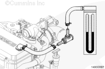
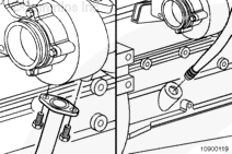
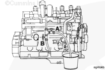
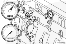
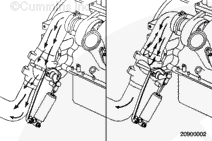
Install a hose assembly with two shutoff valves (A and B), installed as shown in the illustration, between the turbocharger and turbocharger drain line location in the cylinder block. The valves must have a minimum inside diameter of 19 mm [0.75 in]. Place the other hose in a 8 to 9 liter [2 to 3 gal] container.
NOTE: Some turbocharger oil drain tubes are a single one piece tube. It can be necessary to create a turbocharger isolation tool. Use a new or used turbocharger drain line and cut a middle section out of the turbocharger drain line to fit the check valves and hoses.
Close the valve (A) that allows oil to drain into the bucket.
Operate the engine at rated speed and under load by either:
For engine testing, a chassis dynamometer or engine dynamometer
A stall speed test (for engines equipped with automatic transmissions only).
Operate the engine at rated rpm and full load until a steady reading is obtained.
NOTE: When measuring blowby, the value can “spike” initially as the engine reaches peak power and rated speed. Wait for the blowby measurement to stabilize before taking a reading.
To reduce the possibility of personal injury, keep hands, long hair, jewelry, and loose fitting or torn clothing away from fans and other moving parts.
WARNING
Troubleshooting presents the risk of equipment damage, personal injury, or death. Troubleshooting must be performed by trained, experienced technicians.
CAUTION
Do not operate the engine with valve (A) open and valve (B) closed for more than 1 minute. Monitor the amount of oil accumulating in the bucket. The engine can run out of lubricating engine oil and severe engine damage will occur.
Do not operate the engine for more than 1 minute. Monitor the amount of oil accumulating in the container. The engine can be run out of lubricating engine oil and severe engine damage will result.
Alternate Turbocharger Isolation Method:
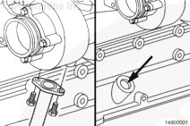
With the turbocharger oil drain line disconnected from the cylinder block, run the turbocharger drain line into a large container.
Plug the turbocharger oil drain port in the cylinder block.
Operate the engine at rated speed and under load by either:
For engine testing, a chassis dynamometer or engine dynamometer
A stall speed test (for engines equipped with automatic transmissions only).
Determine the turbocharger blowby pressure contribution by determining the difference in the blowby pressure measurement with the turbocharger drain isolated, valve (A) open, and turbocharger drain not isolated, valve (A) closed.
Blowby Pressure Differential
Turbocharger Blowby Contribution
Maximum: 30 percent
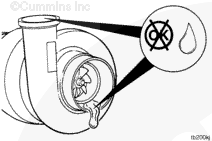
If the turbocharger blowby contribution is out of specification, inspect the compressor and turbine areas of the turbocharger for signs of an oil leak. Replace the turbocharger, if necessary.
Reference the following procedure in the Industrial QSB3.9-30, QSB4.5-30, and QSB5.9-30 Series Engines Troubleshooting and Repair Manual, Bulletin 4021398. Refer to Procedure 010-033 in Section 10.
Reference the following procedure in the ISC, ISCe, QSC8.3, ISL, ISLe3, ISLe4 and QSL9 Engines Troubleshooting and Repair Manual, Bulletin 4021418. Refer to Procedure 010-033 in Section 10.
Reference the following procedure in the B4.5s and B6.7s Series Engines Troubleshooting and Repair Manual, Bulletin 4095243. Refer to Procedure 010-033 in Section 10.
Reference the following procedure in the Industrial QSB3.9-30, QSB4.5-30, and QSB5.9-30 Series Engines Troubleshooting and Repair Manual, Bulletin 4021398. Refer to Procedure 010-045 in Section 10.
Reference the following procedure in the ISC, ISCe, QSC8.3, ISL, ISLe3, ISLe4 and QSL9 Engines Troubleshooting and Repair Manual, Bulletin 4021418. Refer to Procedure 010-045 in Section 10.
Reference the following procedure in the B4.5s and B6.7s Series Engines Troubleshooting and Repair Manual, Bulletin 4095243. Refer to Procedure 010-045 in Section 10.
Wear appropriate eye and face protection when using compressed air. Flying debris and dirt can cause personal injury.
Air Compressor Blowby Contribution:
With the engine blowby service tool and water manometer or pressure gauge still installed, isolate the air compressor, if equipped, to determine if there is internal damage to the air compressor contributing to high engine crankcase pressure. The air compressor can be isolated by unloading the air compressor.
With the engine shut off, bleed the vehicle’s air system down by opening the drain cock on the wet tank to release compressed air from the system.
NOTE: The air compressor governor/unloader location can vary on each engine application. The air governor/unloader can be air compressor mounted or chassis mounted.
Disconnect the air signal line from the air compressor governor/unloader air signal port.
Disconnect the air compressor discharge line and air intake hose from the air compressor.
NOTE: On turbocharged air compressors, make sure to plug the air intake hose connected to the engine intake manifold or the engine will not reach full power during test.
To unload the air compressor, determine the pressure needed at the governor/unloader air signal port to start and stop the air compressor from pumping.
NOTE: Typical 621 kPa [90 psi] of air pressure is the set point between starting and stopping of the air compressor pumping. Refer to the OEM service manual.
Connect a regulated shop air pressure line, with pressure gauge, to the air compressor governor/unloader air signal port.
NOTE: When performing the test, make sure that the air system pressure does not exceed the manufacturer’s maximum allowable pressure.
Run the engine and increase the signal pressure to the air governor/unloader to determine when the air compressor will stop pumping (system pressure stops rising at this point). Record the signal line pressure.
Reduce the signal pressure to determine when system pressure starts the air compressor pumping again (system pressure will begin to rise again at this point). Record the signal line pressure.
NOTE: Allow the air compressor to pump long enough to build enough pressure in the system to release and operate the air brakes.
With the regulated shop air pressure line still connected to the air compressor governor/unloader air signal port, regulate the signal pressure so that the air compressor starts pumping (system pressure will begin to rise again at this point). Use the pressure value recorded previously as a set point.
Operate the engine at rated speed and under load by either:
For engine testing, a chassis dynamometer or engine dynamometer.
A stall speed test (for engines equipped with automatic transmissions only).
Operate the engine at rated rpm and full load until a steady reading is obtained.
NOTE: When measuring blowby, the value can “spike” initially as the engine reaches peak power and rated speed. Wait for the blowby measurement to stabilize before taking a reading.
Continue operating the engine at rated speed and load.
Increase the signal pressure (system pressure stops rising at this point). Use the pressure value recorded previously as a set point.
Operate the engine at rated rpm and full load until a steady reading is obtained.
NOTE: When measuring blowby, the value can “spike” initially as the engine reaches peak power and rated speed. Wait for the blowby measurement to stabilize before taking a reading.
Determine the air compressor blowby pressure contribution by determining the difference in the blowby pressure measurement with the air compressor pumping and the air compressor not pumping.
Blowby Pressure Differential
Air Compressor Contribution
Maximum: 30 percent
If the air compressor blowby contribution is out of specification, replace the air compressor.
Reference the following procedure in the Industrial QSB3.9-30, QSB4.5-30, and QSB5.9-30 Series Engines Troubleshooting and Repair Manual, Bulletin 4021398. Refer to Procedure 012-014 in Section 12.
Reference the following procedure in the ISC, ISCe, QSC8.3, ISL, ISLe3, ISLe4 and QSL9 Engines Troubleshooting and Repair Manual, Bulletin 4021418. Refer to Procedure 012-014 in Section 12.
Disconnect the regulated shop air pressure line, with pressure gauge, from the air compressor governor/unloader air signal port.
Connect the air signal line. Refer to the OEM service manual.
Remove the engine blowby service tool and water manometer or pressure gauge if the blowby is within specification.
NOTE: On turbocharged air compressors, make sure to remove the plug previously installed in the air intake hose connected to the engine intake manifold.
Connect the air compressor discharge line and air intake hose from the air compressor.
NOTE: Not all vehicles are equipped with an exhaust brake.
With the engine blowby service tool and water manometer or pressure gauge still installed, measure blowby pressure during exhaust brake operation, if equipped.
Operate the vehicle going down a long inclined road such as a highway or interstate off ramp. Begin exhaust brake operation at rated engine speed while measuring blowby pressure during exhaust brake operation.
Also, measure exhaust back pressure during exhaust brake operation.
Operate the engine until a steady reading is obtained.
NOTE: When measuring blowby, the value can “spike” initially as the engine reaches peak power and rated speed. Wait for the blowby measurement to stabilize before taking a reading.
If blowby pressure is above specification during exhaust brake operation and exhaust back pressure is above specification, repair or replace the exhaust brake. See the manufacturer’s instructions.
If the blowby pressure is above specification during exhaust brake operation and the exhaust back pressure is within specification, check the turbocharger blowby contribution. Reference the turbocharger oil drain isolation step previously in this procedure.
Remove the engine blowby service tool and water manometer or pressure gauge.
Remove the pressure gauge used to measure exhaust back pressure during exhaust brake operation.
Base engine components can also be contributing factors of increased crankcase blowby and higher than normal crankcase pressure. Use Troubleshooting Symptom Tree t027 (Crankcase Gases (Blowby) Excessive) in the appropriate engine service manual to evaluate the remaining possible causes for increased blowby and higher than normal crankcase pressure. The following are listed as possible Base Engine Component causes:
Reference the following procedure in the ISB and QSB5.9-44 Engines Troubleshooting and Repair Manual, Bulletin 3666193. Refer to Procedure 002-004 in Section 2.
Reference the following procedure in the ISBe, ISB, and QSB (Common Rail Fuel System) Service Manual, Bulletin 4021271. Refer to Procedure 002-004 in Section 2.
Reference the following procedure in the Industrial QSB3.9-30, QSB4.5-30, and QSB5.9-30 Series Engines Troubleshooting and Repair Manual, Bulletin 4021398. Refer to Procedure 002-004 in Section 2.
Reference the following procedure in the ISC, ISCe, QSC8.3, ISL, ISLe3, ISLe4 and QSL9 Engines Troubleshooting and Repair Manual, Bulletin 4021418. Refer to Procedure 002-004 in Section 2.
Reference the following procedure in the Industrial QSB3.9-30, QSB4.5-30, and QSB5.9-30 Series Engines Troubleshooting and Repair Manual, Bulletin 4021398. Refer to Procedure 012-014 in Section 12.
Reference the following procedure in the ISC, ISCe, QSC8.3, ISL, ISLe3, ISLe4 and QSL9 Engines Troubleshooting and Repair Manual, Bulletin 4021418. Refer to Procedure 012-014 in Section 12.
Reference the following procedure in the ISB and QSB5.9-44 Engines Troubleshooting and Repair Manual, Bulletin 3666193. Refer to Procedure 001-043 in Section 1.
Reference the following procedure in the ISBe, ISB, and QSB (Common Rail Fuel System) Service Manual, Bulletin 4021271. Refer to Procedure 001-043 in Section 1.
Reference the following procedure in the Industrial QSB3.9-30, QSB4.5-30, and QSB5.9-30 Series Engines Troubleshooting and Repair Manual, Bulletin 4021398. Refer to Procedure 001-043 in Section 1.
Reference the following procedure in the ISC, ISCe, QSC8.3, ISL, ISLe3, ISLe4 and QSL9 Engines Troubleshooting and Repair Manual, Bulletin 4021418. Refer to Procedure 001-043 in Section 1.
Hello, I'm Jack, a diesel engine fan and a blogger. I write about how to fix and improve diesel engines, from cars to trucks to generators. I also review the newest models and innovations in the diesel market. If you are interested in learning more about diesel engines, check out my blog and leave your feedback.
View all posts by Jack


 CAUTION
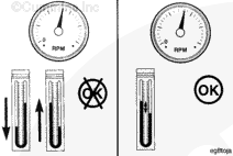

 WARNING
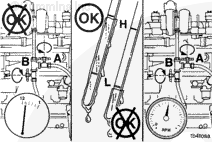

;)
;)
;)
;)
;)
;)
;)
;)
;)
;)
;)
;)
;)
;)
;)
;)
;)
;)
;)
;)
;)
;)
;)
;)
;)
;)
;)
;)
;)
;)
;)
;)
;)
;)
;)
;)
;)
;)
;)
;)
;)
;)
;)
;)
;)
;)
;)
;)
;)
;)
;)
;)
;)
;)
;)
;)
;)
;)
;)
;)
;)
;)
;)
;)
;)
;)