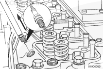
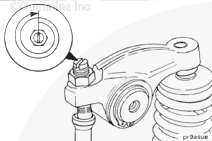
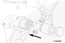
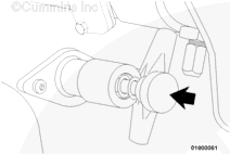
The location of the engine position sensor assembly on the gear housing is critical for correct engine adjustments. Follow this procedure to install the assembly so that it corresponds to top dead center (TDC) for cylinder No. 1.
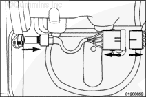
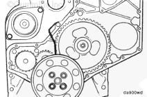
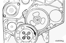
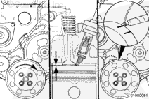
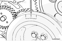
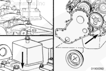
Verify that the No. 1 cylinder is at or near TDC on the compression stroke by rotating the crankshaft until the engine position sensor hole is visible in the cam gear viewed through the gear housing.
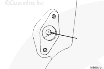
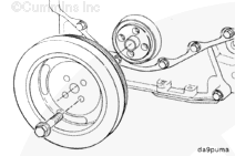
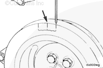
Fabricate and install a wire pointer for the front of the engine. This can be done by forming a piece of wire that can be tightened under one of the gear housing capscrews. The wire should extend from the gear housing to a place on the crankshaft vibration damper that is easily seen.
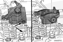
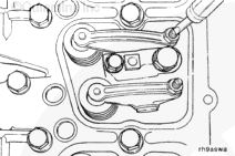
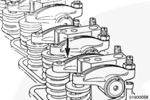
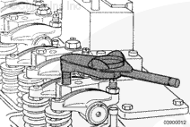
Completely loosen the intake valve adjusting screw. Failure to do so will result in damage to the intake valve or push rod when the crankshaft is rotated.
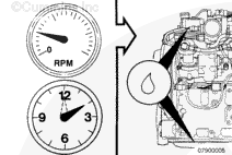
Rotate the crankshaft in the direction of normal engine rotation until the pointer is aligned with the TDC mark, then rotate the crankshaft one additional revolution.
The engine position sensor hole in the cam gear should be visible or felt through the back side of the gear housing. If not, the crankshaft must be rotated one revolution in the direction of engine rotation.
Hello, I'm Jack, a diesel engine fan and a blogger. I write about how to fix and improve diesel engines, from cars to trucks to generators. I also review the newest models and innovations in the diesel market. If you are interested in learning more about diesel engines, check out my blog and leave your feedback.
View all posts by Jack


 CAUTION
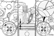


;)
;)
;)
;)
;)
;)
;)
;)
;)
;)
;)
;)
;)
;)
;)
;)
;)
;)
;)
;)
;)
;)
;)
;)
;)
;)
;)
;)
;)
;)
;)
;)
;)
;)
;)
;)
;)
;)
;)
;)
;)
;)