Remove
TOC
15 mm
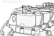
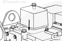
Remove the rocker lever covers.
14 mm
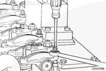
Loosen the adjusting screw locknuts. Loosen the adjusting screws until they stop.
13 mm, 18 mm
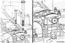
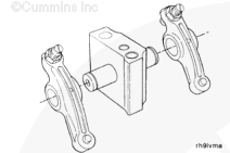
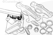
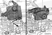
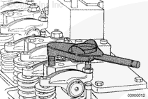
Remove the capscrews from the rocker lever pedestals. Remove the pedestals and rocker lever assemblies.
Disassemble
TOC
If the rocker lever and push tubes are to be inspected for reuse, follow these steps.
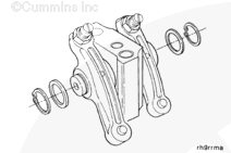
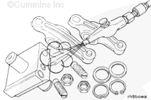
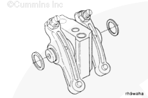
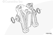
Remove the retaining rings and thrust washers.
CAUTION
Do not disassemble the rocker lever shaft and pedestal. The pedestal and shaft must be replaced as an assembly.
Inspect for Reuse
TOC
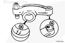
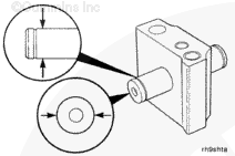
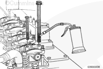
Inspect the pedestal and shaft.
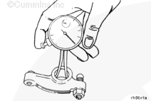
Measure the shaft diameter.
Rocker Lever Shaft
mm
in
18.94
MIN
0.746
Assemble
TOC
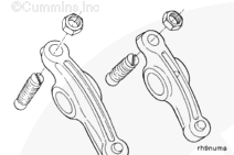
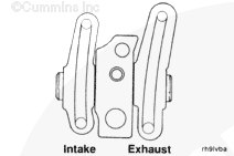
NOTE : Be sure to assemble the intake and exhaust rocker levers in the correct location.
Install
TOC
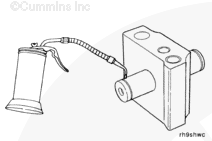
Make sure the dowel rings in the pedestals are installed into the dowel bores.
Inspect all cylinder head capscrews for proper length using Service Tool Part No. 3823921.
Use clean engine oil to lubricate the threads and under the heads of the capscrews.
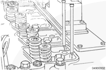
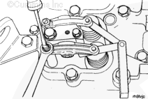
Install the capscrews into the pedestals.
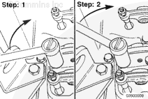
Step 1: Tighten all the cylinder head capscrews to 90 N•m [66 ft-lb].
Step 2:(Long cylinder head capscrews only) Tighten the cylinder head capscrews to 120 N•m [90 ft-lb].
18 mm
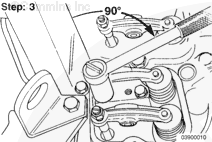
Step 3:
After the long cylinder head capscrews have been tightened to 120 N•m
13 mm
Tighten the 8 mm pedestal capscrews.
Torque Value: 24 n.m [18 ft-lb]
Install the rocker lever covers.
Torque Value: 24 n.m [18 ft-lb]
Last Modified: 27-Jun-2002
Published by Jack
Hello, I'm Jack, a diesel engine fan and a blogger. I write about how to fix and improve diesel engines, from cars to trucks to generators. I also review the newest models and innovations in the diesel market. If you are interested in learning more about diesel engines, check out my blog and leave your feedback.
View all posts by Jack


 CAUTION
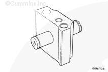


;)
;)
;)
;)
;)
;)
;)
;)
;)
;)
;)
;)
;)
;)
;)
;)
;)
;)
;)
;)
;)
;)
;)
;)
;)
;)
;)
;)
;)
;)
;)
;)
;)
;)
;)
;)
;)
;)
;)
;)
;)
;)
;)
;)
;)
;)
;)
;)