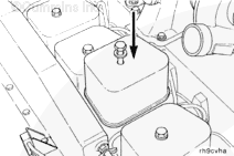
The rocker lever group consists of the rocker lever assemblies, rocker assembly oil manifold, valve cover, and crankcase breather.
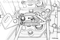
Each cylinder of the engine has a separate rocker lever assembly. The pedestal support has drillings to route the oil flow to the shaft and levers.
The rocker levers are push tube actuated and use an adjusting screw to control the clearance between the rocker lever and valve stem. The rocker levers do not use a bushing in the bore for the rocker lever shaft. The rocker lever must be replaced if the bore is damaged or worn beyond the specification limit.
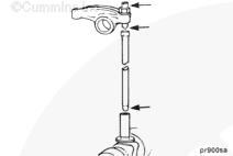
The ball end of the push tube fits into the ball socket in the tappet. The other end of the push rod has a ball socket in which the ball end of the rocker lever adjusting screw operates.
NOTE: The phosphorous and zinc levels in MidRange natural gas engine oils help in the lubricating of sliding tappets.
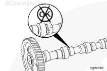
Loose rocker levers and the need to reset the valve clearance frequently can also indicate camshaft lobe or tappet wear. If an inspection of the rocker levers, valve stems, and push tubes does not show wear, then tappet and/or camshaft lobe wear can be suspected. Refer to Procedure 001-008 and Refer to Procedure 004-015.
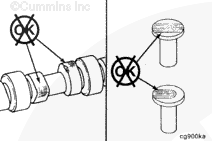
A severely damaged camshaft journal(s) can generate metal chips that will be found in the lubricating oil pan and oil filter.
NOTE: As the clearance between the camshaft bushing(s) and camshaft journal(s) increases, oil pressure and volume will decrease, causing damage to the camshaft and tappets.
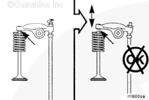
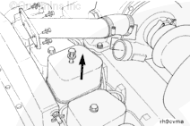
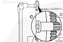
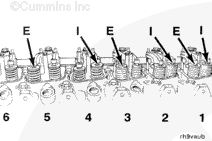
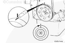
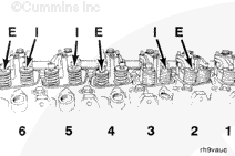
Use a 1/2-inch drive, Engine Barring Tool, Part Number 3824591 to rotate the engine (clockwise when facing the damper) until cylinder Number 4 (for 4 cylinder) or cylinder Number 6 (for 6 cylinder) intake rocker arm starts to open the intake valve.
Wiggle the rocker arm while barring the engine; when the rocker arm gets tight, stop barring.
NOTE: On the liquefied petroleum gas application, the evaporator must be removed in order to use the engine barring tool.
Hello, I'm Jack, a diesel engine fan and a blogger. I write about how to fix and improve diesel engines, from cars to trucks to generators. I also review the newest models and innovations in the diesel market. If you are interested in learning more about diesel engines, check out my blog and leave your feedback.
View all posts by Jack


 CAUTION


;)
;)
;)
;)
;)
;)
;)
;)
;)
;)
;)
;)
;)
;)
;)
;)
;)
;)
;)
;)
;)
;)
;)
;)