B5.9G, B5.9LPG – Troubleshooting and Repair Manual – 004-015   Tappet

Preparatory Steps

TOC

  • Remove the rocker lever cover. Refer to Procedure 003-011.
  • Remove the rocker levers. Refer to Procedure 003-008.
  • Remove the push tubes. Refer to Procedure 004-014.
  • Remove the crankshaft pulley. Refer to Procedure 001-022.
  • Remove the vibration damper. Refer to Procedure 001-052.
  • Remove the gear cover. Refer to Procedure 001-031.
  • Remove the camshaft. Refer to Procedure 001-008.
 
SMALL | MEDIUM | LARGE

Remove

TOC

Tappet Replacement Kit, Part Number 3822513

Insert the trough from the tappet replacement kit, Part Number 3822513, to the full length of the cam bore.

SMALL | MEDIUM | LARGE


NOTE: Number each tappet with the cylinder number position as it is removed. Tappets must be installed in the same position as removed.

Make sure the trough is positioned so it will catch the tappet when the wooden dowel is removed.

 
SMALL | MEDIUM | LARGE


Only remove one tappet at a time. Remove the rubber band from the two companion tappets, securing the tappet not to be removed with the rubber band.

SMALL | MEDIUM | LARGE


Pull the wooden dowel from the tappet bore, allowing the tappet to fall into the trough.

SMALL | MEDIUM | LARGE


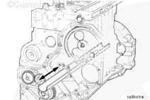
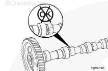
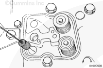
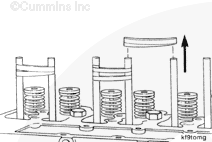
When the tappet is dropped into the trough, most of the time it will fall over. However, if it does not, gently shake the trough just enough to allow the tappet to fall over before removing.

 
SMALL | MEDIUM | LARGE


NOTE: When removing the number 6 cylinder tappets, take special care not to knock or shake the tappet over the end of the trough.

SMALL | MEDIUM | LARGE


Carefully pull the trough and tappet from the cam bore, and remove the tappet. Repeat the process until all tappets are removed.

SMALL | MEDIUM | LARGE
   

Inspect for Reuse

TOC

 CAUTION 

Anytime a new camshaft is installed, new tappets and push tubes must also be installed.

SMALL | MEDIUM | LARGE


 CAUTION 

If some of the tappets are found to be in need of replacing, the corresponding push tubes must also be replaced. Failure to do so can cause severe engine damage.

SMALL | MEDIUM | LARGE


Inspect the socket, stem, and face for excessive wear, cracks, and other damage.

Visual Limits
(A) Normal contact (exaggerated)
(B and C) Irregular contact: Do not reuse.

SMALL | MEDIUM | LARGE


Pit marks on the tappet face are acceptable.

The following criteria define the size of the pits allowed.

  1. A single pit can not be greater than 2 mm [0.079 in].
  2. Interconnection of pits is not allowed.
  3. Total pits when added together should not exceed 6-mm
    [0.236-in] diameter or a total of 4 percent of the tappet face.
  4. No pitting is allowed on the edges of the wear face of the tappet.

SMALL | MEDIUM | LARGE


Measure the valve tappet stem.

Valve Tappet Stem Diameter
mm in
15.936 MIN 0.627
15.977 MAX 0.629

SMALL | MEDIUM | LARGE
   

Install

TOC

Insert the trough the full length of the cam bore.

SMALL | MEDIUM | LARGE


Lower the tappet installation tool down the push tube hole, through the tappet bore, and into the trough.

SMALL | MEDIUM | LARGE


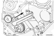
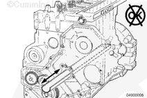
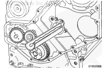
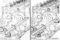
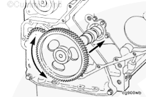
Feed the installation tool through the cam bores by carefully pulling the trough/installation tool out the front. The barrier at the rear of the trough will pull the tool out most of the time.

SMALL | MEDIUM | LARGE


NOTE: If the tappets have previously been used, each tappet must
be installed in the same position as it was removed from the engine.

Lubricate the tappets with Lubriplate™ 105.

SMALL | MEDIUM | LARGE


Insert the installation tool into the tappet.

NOTE: To aid in removing the installation tool after the tappet is installed, work the tool in and out of the tappet several times before installing the tappets.

SMALL | MEDIUM | LARGE


Slide the trough into the cam bore.

SMALL | MEDIUM | LARGE


Pull the tool and tappet through the cam bore and up into the tappet bore.

SMALL | MEDIUM | LARGE


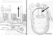
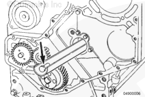
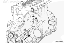
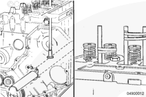
If difficulty is experienced in getting the tappet to make the bend from the trough up to the tappet bore, pull the trough out enough to allow the tappet to drop down and align itself; then, pull the tappet up into the bore.

SMALL | MEDIUM | LARGE


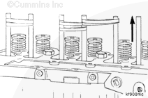
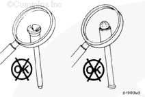
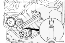
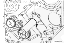
After the tappet has been pulled up into position, slide the trough back into the cam bore, and rotate it one-half of a turn. This will position the round side of the trough up, which will hold the tappet in place.

 
SMALL | MEDIUM | LARGE


Remove the installation tool from the tappet.

SMALL | MEDIUM | LARGE


Install a wooden dowel into the top of the tappet. Wrap rubber bands around the wooden dowels to secure the tappets.

Repeat this process until all tappets have been installed.

SMALL | MEDIUM | LARGE


Install the camshaft. Refer to Procedure 001-008.

SMALL | MEDIUM | LARGE


Remove the dowel rods and release the tappets in the tappet bores.

SMALL | MEDIUM | LARGE


  • Install the gear cover. Refer to Procedure 001-031.
  • Install the crankcase pulley. Refer to Procedure 001-022.
  • Install the vibration damper. Refer to Procedure 001-052.
  • Install the push tubes. Refer to Procedure 004-014.
  • Install the rocker levers. Refer to Procedure 003-008.
  • Adjust the valves. Refer to Procedure 003-004.
  • Install the rocker lever cover(s). Refer to Procedure 003-011.

SMALL | MEDIUM | LARGE


Fill the engine with clean gas engine lubricating oil and coolant. Refer to Procedures 007-025 and 008-018.

Operate the engine until the coolant temperature reaches 82°C [180°F], and check for leaks and proper operation.

Add coolant and lubricating engine oil, if necessary, to reach correct levels.

SMALL | MEDIUM | LARGE
Last Modified:  27-Jun-2002