Cylinder liners of different design can not be mixed within an engine. All six cylinder liners must be of the same design.
There are two different designs of cylinder liners used. The design used in a particular engine is dependent on the engine’s production vintage.
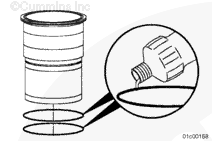
Engines assembled prior to engine serial number 14022615 have groove-top cylinder liners. They are characterized by a groove machined into the top surface of the cylinder liner flange.
Engines with serial number 14022615, and after, are assembled with flat-top cylinder liners. They are characterized by a cylinder liner flange that is flat, except for the fire dam.
Cylinder liners of different design can not be mixed within an engine. All six cylinder liners must be of the same design.
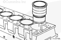
Install the cylinder liner into the cylinder block.
When acceptable and used cylinder liners are installed, rotate the cylinder liner 90 degrees from its original position in the engine. The thrust and anti-thrust surfaces must face the front and back of the cylinder block.
Use cylinder liner installation kit, Part Number 3162461, to seat the liner.
If the cylinder liner does not seat properly, remove it and inspect the cylinder liner bore seat and cylinder liner for nicks, burrs, or dirt.
Because of design differences, the cylinder liner’s position (relative to the cylinder top deck) will be different.
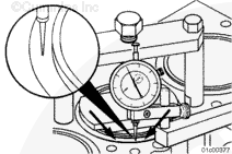
For groove-top cylinder liners, a recession measurement is taken. This measures the depth of the groove relative to the cylinder block deck regardless of the flange or fire dam height.
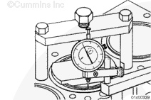
For flat-top cylinder liners, a cylinder liner protrusion measurement is taken which is the height of the cylinder liner flange above the cylinder block surface regardless of the flange or fire dam height.
Regardless of the cylinder liner design, the measurement technique will be the same.
Hello, I'm Jack, a diesel engine fan and a blogger. I write about how to fix and improve diesel engines, from cars to trucks to generators. I also review the newest models and innovations in the diesel market. If you are interested in learning more about diesel engines, check out my blog and leave your feedback.
View all posts by Jack
 CAUTION






;)
;)
;)
;)
;)
;)
;)
;)
;)
;)
;)
;)
;)
;)