The cylinder block saddle and the cap mating surfaces must be clean and dry when the bearing shells are installed. Used bearings must be installed in their original location or engine damage can occur.
CAUTION
The bearing tang must fit into the slot in the bearing saddle or engine damage can occur.
CAUTION
Do not use a capscrew or any hard metal object to install bearings, as this can damage the crankshaft and cause an engine failure.
Use clean Lubriplate™ 105 multi-purpose lubricant, or its equivalent, to lubricate the upper main bearing shell to crankshaft journal mating surface.
Start the bearing into the upper saddle by hand. Slide the bearing into position. Take care to not damage the crankshaft journal while installing the bearing.
Use clean Lubriplate™ 105 multi-purpose lubricant, or its equivalent, to lubricate the inside diameter of the bearing shells and the liner side of the upper thrust bearings.
Make sure the bevel side is toward the crankshaft journal. Incorrect thrust bearing installation will result in engine damage.
Install the upper thrust bearings in the number four main bearing saddle.
Push the crankshaft toward the rear of the engine to install the front thrust bearing and toward the front of the engine to install the rear thrust bearing.
Only use Loctite™ 518 thread sealant on the main cap joint mating surface. Other sealants can become hard, brittle, and allow oil and debris into the main bearing/block joint, causing engine damage.
CAUTION
The bead must be 3 to 5 mm [0.12 to 0.20 in] wide and must not enter the main bearing shell inside the main bearing shell inside diameter. Sealant in the main bearing can cause engine damage.
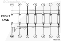
Apply a bead of Loctite™ 518 thread sealant to the two main bearing cap surfaces on each main bearing cap as shown.
The main bearing caps are marked with a `V.’ Position the `V’ mark so that it points to the front of the engine. Incorrect positioning will result in severe engine damage.
Align the capscrew holes in the cap with the holes in the cylinder block. Make sure the lower bearing shell is in position.
Install the capscrews through the cap and into the cylinder block.
To reduce the possibility of bore size issues, clearance issues, or both, the main bearing capscrews must be tightened within 15 minutes of the Loctite™ 518 thread sealant application.
Crankshafts that have been reground on the thrust bearing surfaces are marked for oversize thrust bearings on the rear crankshaft counterweight. If the crankshaft counterweight is marked, check the thrust ring part number to make sure the correct thrust ring size is used.
Hello, I'm Jack, a diesel engine fan and a blogger. I write about how to fix and improve diesel engines, from cars to trucks to generators. I also review the newest models and innovations in the diesel market. If you are interested in learning more about diesel engines, check out my blog and leave your feedback.
View all posts by Jack
 CAUTION




;)
;)
;)
;)
;)
;)
;)
;)
;)
;)
;)
;)
;)
;)
;)
;)
;)
;)
;)
;)
;)
;)
;)
;)
;)
;)
;)
;)
;)
;)
;)
;)
;)
;)
;)
;)
;)
;)
