Centinel System – Repair Manual – 001-005   Bearings, Connecting Rod

View Related Topic


Preparatory Steps

TOC

 WARNING 

To reduce the possibility of personal injury, avoid direct contact of hot oil with your skin.
 WARNING 

Some state and federal agencies have determined that used engine oil can be carcinogenic and cause reproductive toxicity. Avoid inhalation of vapors, ingestion, and prolonged contact with used engine oil. If not reused, dispose of in accordance with local environmental regulations.
  • Drain the lubricating oil. Refer to Procedure
    007-037.
  • Remove the lubricating oil pan. Refer to Procedure
    007-025.
  • Remove the lubricating oil suction tube. Refer to Procedure
    007-035.
  • Remove the lubricating oil pump. Refer to Procedure
    007-031.
  • Remove the block stiffener plate. Refer to Procedure
    001-089.
  • Remove the piston cooling nozzles. Refer to Procedure
    001-046.

SMALL | MEDIUM | LARGE

Remove

TOC

Rotate the crankshaft so that two of the connecting rods are at bottom dead center.

 
SMALL | MEDIUM | LARGE


Do
not remove the capscrews at this time.

Loosen the connecting rod capscrews.

Hit the connecting rod capscrews with a rubber hammer to loosen the rod caps from the dowels.

 
SMALL | MEDIUM | LARGE


Remove the capscrews and the rod cap.

Remove the bearing shell from the rod cap and mark the cylinder number and the letter “L” on the flat surface of the bearing tangs.

SMALL | MEDIUM | LARGE


Install two guide pins, Part Number 3163097, in the connecting rod.

Push the rod up far enough to allow the upper bearing shell to be removed. Use a T-handle piston pusher.

Remove the bearing shell and mark the cylinder number and the letter “U” on the flat surface of the bearing tangs.

SMALL | MEDIUM | LARGE
   

Clean and Inspect for Reuse

TOC

 WARNING 

Wear appropriate eye and face protection when using compressed air. Flying debris and dirt can cause personal injury.
 WARNING 

When using a steam cleaner, wear safety glasses or a face shield, as well as protective clothing. Hot steam can cause serious personal injury.

Steam-clean the parts and dry with compressed air.

SMALL | MEDIUM | LARGE


Inspect the rod caps, connecting rod bearing saddles, and capscrews for nicks, cracks, burrs, scratches, or fretting.

SMALL | MEDIUM | LARGE


Inspect the connecting rod journal of the crankshaft for scratches or nicks.

Use crocus cloth to remove the nicks and scratches.

SMALL | MEDIUM | LARGE


Inspect the bearings for damage.

Replace any bearings with the following damage:

  • Pitting
  • Flaking
  • Corrosion
  • Lock tang damage
  • Scratches (deep enough to be felt with a fingernail).

SMALL | MEDIUM | LARGE


Normal bearing wear produces a smooth finish that will wear into the lining. Refer to the Parts Reuse Guidelines, Bulletin 3810303.

SMALL | MEDIUM | LARGE


For more detailed information of bearing damage, refer to Analysis and Prevention of Bearing Failures, Bulletin 3810387.

Inspect the bearing seating surface for nicks or burrs.

If nicks or burrs can
not be removed with a fine crocus cloth, the bearings
must be replaced.

SMALL | MEDIUM | LARGE


Measure the rod bearing shell thickness with an outside micrometer that has a ball tip.

Discard a bearing shell if its thickness is below the minimum specification.

Standard Connecting Rod Bearing Thickness
mm in
2.366 MIN 0.093
2.378 MAX 0.094

SMALL | MEDIUM | LARGE


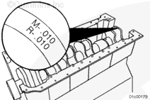
Crankshafts that are ground undersize in the connecting rod or the main bearing journals are marked on the front counterweight. If the crankshaft is marked, check the bearing shell part number to make sure the correct bearing size is used.

SMALL | MEDIUM | LARGE
   

Install

TOC

 CAUTION 

Connecting rod bearings must match the connecting rod design. Drilled rods must use drilled rod bearings. Non-drilled rods must use non-drilled bearings. Mismatches will cause engine damage.

Connecting rod design
must be matched with the proper connecting rod bearing.

Drilled connecting rods
must be fitted with drilled connecting rod bearings.

Non-drilled connecting rods
must be fitted with non-drilled connecting rod bearings.

SMALL | MEDIUM | LARGE


Drilled and non-drilled connecting rods can be mixed in the same engine as long as the two piece piston is used.

Engines using single piece pistons can
not use non-drilled connecting rods.

 
SMALL | MEDIUM | LARGE


 CAUTION 

The connecting rod and bearing shell mating surfaces must be clean and dry when the bearing shells are installed. Used bearings must be installed in their original location or engine damage can occur.

Use clean Lubriplate™ 105 multi-purpose lubricant, or its equivalent to lubricate the crankshaft journal mating surface of the upper bearing shell.

Install the upper bearing shell into the connecting rod with the tang of the bearing in the slot of the rod.

SMALL | MEDIUM | LARGE


Install the bearing shell into the connecting rod cap with the tang (2) of the bearing in the slot (1) of the cap.

Use clean Lubriplate™ 105 multi-purpose lubricant, or its equivalent to lubricate the bearing shell to crankshaft journal mating surface and the connecting rod capscrews.

SMALL | MEDIUM | LARGE


 CAUTION 

The rod cap alpha characters must match the alpha characters on the connecting rod and must be installed with the characters aligned to prevent damage to the connecting rods and crankshaft. The locking tang of the connecting rod cap must face toward the intake side of the cylinder block. Rod and cap mating surfaces must be clean or engine damage can occur.

Install the cap onto the connecting rod.

SMALL | MEDIUM | LARGE


Lubricate the threads of the capscrews with clean engine oil.

Thread the capscrews into the connecting rod and hand tighten.

The procedure for tightening used capscrews is different than the procedure for tightening new capscrews.

For used connecting rod capscrews:

Tighten Capscrews in Numerical Sequence

  Step 2 70 ± 6 n.m   [52 ± 4 ft-lb]
  Step 3 Rotate capscrews in numerical sequence 60 ± 5 degrees

For new connecting rod capscrews:

Tighten Capscrews in Numerical Sequence

  Step 2 40 ± 6 n.m   [29 ± 4 ft-lb]
  Step 3 Loosen capscrews in numerical sequence
  Step 4 70 ± 6 n.m   [52 ± 4 ft-lb]
  Step 5 Rotate capscrews in numerical sequence 60 ± 5 degrees

SMALL | MEDIUM | LARGE


Measure the connecting rod side clearance.

Connecting Rod Side Clearance
mm   in
0.10 MIN 0.004
0.33 MAX 0.013

NOTE: The connecting rod
must move freely from side to side on the crankshaft journal. If the rod does
not move freely, remove the rod cap and make sure the bearing shells are the correct size. Check for dirt or damage on the crankshaft and the bearing shells.

Repeat the above steps to install the remaining bearing shells and connecting rod caps.

SMALL | MEDIUM | LARGE
   

Finishing Steps

TOC

 CAUTION 

The lubricating oil system must be primed before operating the engine after any internal engine repairs to avoid internal component damage.
  • Install the piston cooling nozzles. Refer to Procedure
    001-046.
  • Install the oil pump. Refer to Procedure
    007-031.
  • Install the block stiffener plate. Refer to Procedure
    001-089.
  • Install the lubricating oil suction tube. Refer to Procedure
    007-035.
  • Install the lubricating oil pan. Refer to Procedure
    007-025.
  • Prime the lubricating oil system. Refer to Procedure
    007-037.
  • Operate the engine until it reaches a temperature of 82°C [180°F], and check for lubricating oil leaks.

SMALL | MEDIUM | LARGE
Last Modified:  08-Mar-2007