Centinel System – Repair Manual – 007-031   Lubricating Oil Pump

Preparatory Steps

TOC

 WARNING 

To reduce the possibility of personal injury, avoid direct contact of hot oil with your skin.
 WARNING 

Some state and federal agencies have determined that used engine oil can be carcinogenic and cause reproductive toxicity. Avoid inhalation of vapors, ingestion and prolonged contact with used engine oil. If not reused, dispose of in accordance with local environmental regulations.

SMALL | MEDIUM | LARGE

Remove

TOC

 CAUTION 
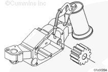
Do not discard shims, if equipped. They must be installed in the original location. Failure to do so can result in engine damage.

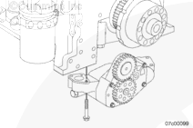
Remove four capscrews, oil pump, and shims if equipped.

When installing a new oil pump, new shims will possibly be needed to acquire acceptable lash.

SMALL | MEDIUM | LARGE
   

Disassemble

TOC

 WARNING 

The pressure regulator spring is under compression. Slowly remove the cap to reduce the possibility of personal injury.

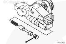
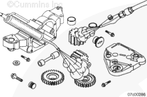
Remove the lubricating oil pressure regulator and spring by removing the split pin that secures the spring cap to the lubricating oil pump.

Discard the o-ring.

SMALL | MEDIUM | LARGE


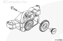
The external idler gear retaining capscrew has a left-hand thread. capscrew.

Remove the external idler gear from the lubricating oil pump.

Save the retaining capscrew for reuse.

SMALL | MEDIUM | LARGE


 WARNING 

The high pressure relief valve is under compression. Apply pressure to the cover while removing the capscrews. Slowly release the pressure to reduce the possibility of personal injury.

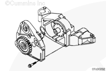
Remove the six assembly capscrews and the lube pump cover.

SMALL | MEDIUM | LARGE


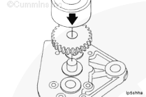
Press off the external drive gear from the internal drive gear shaft.

SMALL | MEDIUM | LARGE


Remove the high-pressure relief spring and ball.

SMALL | MEDIUM | LARGE


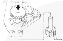
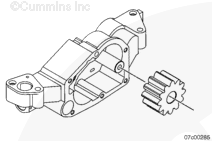
Remove the idler pumping gear from the shaft in the lubricating oil pump body.

SMALL | MEDIUM | LARGE
   

Clean and Inspect for Reuse

TOC

 WARNING 

When using solvents, acids, or alkaline materials for cleaning, follow the manufacturer’s recommendations for use. Wear goggles and protective clothing to reduce the possibility of personal injury.
 WARNING 

Some solvents are flammable and toxic. Read the manufacturer’s instructions before using.
 CAUTION 
Do not allow dirt or gasket material to enter the oil passages. Bearing damage can result.

Clean the lubricating oil pump components with solvent.

Use a bristle brush to clean any internal ports.

SMALL | MEDIUM | LARGE


 WARNING 

When using a steam cleaner, wear safety glasses or a face shield, as well as protective clothing. Hot steam can cause serious personal injury.
 WARNING 

Wear appropriate eye and face protection when using compressed air. Flying debris and dirt can cause personal injury.

Use a steam cleaner to rinse the components.

Dry with compressed air.

SMALL | MEDIUM | LARGE


Inspect the following areas of the lubricating oil pump for damage or blockage.

  • Lubricating oil pump body gear cavity
  • Inlet and outlet ports
  • Internal oil passages
  • Lubricating oil pump housing body
  • Pressure regulator bore
  • High pressure relief bore and seat.

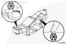
If the lubricating pump housing is damaged, it must be replaced.

SMALL | MEDIUM | LARGE


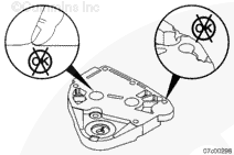
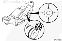
Inspect the lubricating oil pump cover for damage.

Inspect the bushing for scuffing and wear.

If the marks on the lubricating pump cover can be felt with a fingernail, the part must be replaced.

SMALL | MEDIUM | LARGE


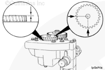
Measure the regulator bore for beat-in.

Regulator Bore Depth Specification

mm in
186.95 MIN 7.3602
187.45 MAX 7.380

If the regulator bore depth is not within the specifications, the housing must be replaced.

SMALL | MEDIUM | LARGE


Inspect the pressure regulator spool for scuffing.

Minor spool scuff is acceptable. If the scuff can be felt by a fingernail, the spool will need to be replaced.

Insert the spool in the bore and check for smooth movement in and out of the bore. If any hesitation is felt, the spool must be replaced and the bore inspected for burrs.

Remove any burrs found in the bore before installing a new spool.

SMALL | MEDIUM | LARGE


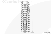
Inspect the pressure regulator spring for a broken coil or rust.

SMALL | MEDIUM | LARGE


Measure the free length of the pressure regulator spring.

Oil Pressure Regulator Spring Free Length

mm in
109.55 NOM 4.313

SMALL | MEDIUM | LARGE


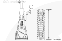
Use a spring compression tester, Part Number 3375182, to measure the pressure regulator valve spring at working height, 70 mm [2.756 in].

Lubricating Oil Pressure Regulator Spring Load at 70 mm [2.756 in]

n lbf
131.8 MIN 29.6
135.3 MAX 30.4

If the regulator spring is not within the specifications, the spring must be replaced.

SMALL | MEDIUM | LARGE


Inspect the high pressure relief spring for a broken coil or rust.

SMALL | MEDIUM | LARGE


Measure the free length of the high pressure relief spring.

High Pressure Relief Valve Spring Free Length

mm in
68.91 NOM 2.713

SMALL | MEDIUM | LARGE


Use a spring compression tester, Part Number 3375182, to measure the high pressure relief spring at working height, 45.82 mm [1.804 in].

High Pressure Relief Valve Spring (Compressed Length) Load at 45.82 mm [1.804 in]

n lbf
281.5 MIN 63.3
298.9 MAX 67.2

If the pressure relief valve spring is not within the specification, the spring must be replaced.

SMALL | MEDIUM | LARGE


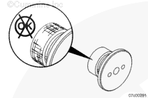
Inspect the high pressure relief ball. A slight ring around the ball from contact with the pump body and spring is acceptable.

SMALL | MEDIUM | LARGE


Inspect the external idler gear retainer.

Minor retainer scuff is acceptable. If the scuff can be felt by a fingernail, replace the retainer.

SMALL | MEDIUM | LARGE


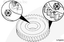
Inspect the external idler gear for cracks, chips, and broken teeth.

If the external idler gear is damaged, the gear must be replaced.

Check the idler gear bushing for wear and scuffing.

SMALL | MEDIUM | LARGE


Measure the inside diameter of the bushing in the external idler gear.

External Idler Gear Bushing Inside Diameter

mm in
32.044 MIN 1.2616
32.069 MAX 1.2626

If the external idler gear bushing is not within specifications, the bushing must be replaced.

SMALL | MEDIUM | LARGE


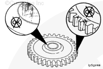
Inspect the external drive gear for cracks, chips, and broken teeth.

If the external drive gear is damaged, the gear must be replaced.

Check the drive gear bushing for wear and scuffing.

SMALL | MEDIUM | LARGE


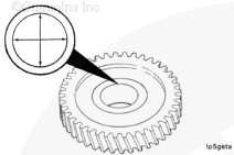
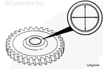
Measure the inside diameter of the external drive gear.

External Drive Gear Inside Diameter (No Bushing)

mm in
24.909 MIN 0.9807
24.935 MAX 0.9817

If the external drive gear is not within specifications, the gear must be replaced.

SMALL | MEDIUM | LARGE


Inspect the lubricating oil pump internal gears for excessive wear, cracks, or broken teeth.

Erosion and pitting on the tip and root of the gear tooth is not acceptable. The gear must be replaced.

SMALL | MEDIUM | LARGE


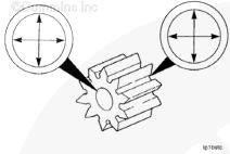
Measure the inside diameter of the internal idler gear.

Internal Idler Gear Inside Diameter

mm in
24.909 MIN 0.9807
24.935 MAX 0.9817

If the internal idler gear is not within specifications, it must be replaced.

SMALL | MEDIUM | LARGE


Inspect the internal idler shaft for damage. Measure the outside diameter of the idler shaft.

Internal Idler Shaft Outside Diameter

mm in
24.858 MIN 0.9787
24.871 MAX 0.9792

If the idler shaft is not within specifications, it must be replaced.

SMALL | MEDIUM | LARGE


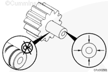
Inspect the internal drive gear and shaft assembly for damage. Measure the outside diameter of the internal drive gear shaft.

Internal Drive Gear Shaft Outside Diameter

mm in
24.858 MIN 0.9787
24.871 MAX 0.9792

If the drive shaft is not within specifications, it must be replaced.

SMALL | MEDIUM | LARGE
   

Assemble

TOC

Lubricate the drive shaft with clean 15W-40 lubricating oil.

Install the internal idler gear onto the shaft.

SMALL | MEDIUM | LARGE


Insert the internal drive gear and shaft assembly into the lubricating oil pump cover.

Press the external drive gear onto the shaft.

SMALL | MEDIUM | LARGE


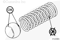
Install the ball first, then the spring.

Install the high pressure relief ball and spring into its bore in the lube pump housing.

SMALL | MEDIUM | LARGE


No gasket is used when installing the lube pump cover.

Install the cover to the lube pump.

Tighten the center capscrews first, then the outside capscrews.

Install the six capscrews and tighten.

Torque Value:  29  n.m  [21 ft-lb]

SMALL | MEDIUM | LARGE


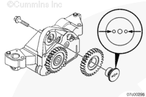
Install the external idler gear.

Insert the external idler gear retainer such that the holes are at the 3 and 9 o’clock position.

The idler gear retaining capscrew has left-hand threads.

Torque Value:  115  n.m  [85 ft-lb]

SMALL | MEDIUM | LARGE


Lubricate the oil pressure regulator valve and bore with clean engine oil.

Install the spring, valve, and cap with a new o-ring.

Use a new split pin to secure the cap to the lubricating oil pump body.

SMALL | MEDIUM | LARGE


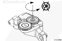
Turn the main drive gear by hand to check the gears for freedom of rotation.

SMALL | MEDIUM | LARGE


Measure the end clearance of the external drive gear.

Drive Shaft End Clearance

mm in
0.100 MIN 0.003
0.163 MAX 0.006

SMALL | MEDIUM | LARGE


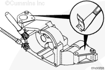
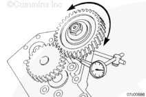
Measure the gear backlash by mounting a dial indicator. Position the dial indicator contact point onto the lubricating oil pump external idler gear teeth.

With the external drive gear locked into place and the dial indicator contact in place, rotate the external idler gear clockwise and counterclockwise to measure the backlash.

Use the backlash measurement to classify and mark the pump per the following table.

Lubricating Oil Pump Gear Backlash
Class
mm
in
1
0.457 to 0.610
0.018 to 0.024
2
0.152 to 0.305
0.006 to 0.012
3
0.000 to 0.152
0.000 to 0.006
4
0.305 to 0.457
0.012 to 0.018

SMALL | MEDIUM | LARGE
   

Install

TOC

Align dowels on oil pump with mounting holes in the cylinder block.

Install the oil pump, shims (if they were removed), and the four capscrews.

Tighten the capscrews.

Torque Value:  56  n.m  [41 ft-lb]

SMALL | MEDIUM | LARGE


Use a dial indicator, check the oil pump idler gear back lash.

Oil Pump Idler Gear Backlash

mm in
0.18 MIN 0.008
0.32 NOM 0.013
0.46 MAX 0.018

SMALL | MEDIUM | LARGE


 CAUTION 

Improper gear lash can cause damage to the gear train and the lubricating oil pump.

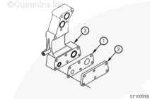
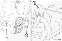
Shims will be available in six different thicknesses in order to provide correct lash. The various thicknesses are identified by the color of the shim. Identify the number stamped on the pump (1) and the letter on the block (2). Use the following table to determine which shim should be used according to the stamped number and letter.

SMALL | MEDIUM | LARGE
   

If a lube pump or cylinder block is replaced, the block and pump will not be stamped. In that instance, a shim must be chosen and installed. The oil pump idler gear backlash must be checked. If the backlash is not within the specification, choose another size shim and recheck the backlash. Do this until the backlash is within specification.

 
Block
Pump
A
B
C
D
1
0.000 mm [0.000 in]-None-
0.45 mm [0.018 in]-Black-
0.55 mm [0.022 in]-Purple-
0.35 mm [0.014 in]-Yellow-
2
0.45 mm [0.018 in]-Black-
0.65 mm [0.026 in]-Red-
0.75 mm [0.030 in]-Blue-
0.55 mm [0.022 in]-Purple-
3
0.55 mm [0.022 in]-Purple-
0.75 mm [0.030 in]-Blue-
0.85 mm [0.033 in]-Green-
0.65 mm [0.026 in]-Red-
4
0.35 mm [0.014 in]-Yellow-
0.55 mm [0.022 in]-Purple-
0.65 mm [0.026 in]-Red-
0.45 mm [0.018 in]-Black-


If the lubricating oil pump is not within specifications, the shims must be changed to proper thickness to give proper backlash.

 
SMALL | MEDIUM | LARGE
   

Finishing Steps

TOC

SMALL | MEDIUM | LARGE
Last Modified:  04-Aug-2009