Use a copper or aluminum vise protector when installing the connecting rod in a vise to protect the connecting rod from damage.
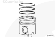
The ring gap of each ring must not be aligned with the piston pin or with any other ring. If the ring gaps are not aligned correctly, the rings will not seal properly.
Place the connecting rod in a vise to hold the assembly in a horizontal position while installing the rings.
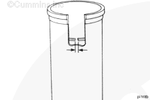
A cross-sectioned view of an oil control ring is shown.
The two-piece oil control ring must be installed with the expander ring gap 180 degrees from the gap of the oil ring. Do not overlap the ends of the expander ring.
Rotate the rings to position the ring gaps as shown.
The ring gap of each ring must not be aligned with the piston pin, or with any other ring gap. If the ring gaps are not aligned correctly, the rings will not seal properly.
Use a copper or aluminum vise protector when installing the connecting rod in a vise to protect the connecting rod from damage.
The ring gap of each ring must not be aligned with the piston pin or with any other ring. If the ring gaps are not aligned correctly, the rings will not seal properly.
Install the connecting rod in a vise to hold the assembly in a horizontal position while installing the rings.
A cross-sectioned view of an oil control ring is shown.
The two-piece oil control ring must be installed with the expander ring gap 180 degrees from the gap of the oil ring. Do not overlap the ends of the expander ring.
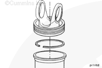
The piston must be held in a horizontal position to install the rings in order to keep the rings in the groove while installing the ring compressor.
The single-piece ring set is similar to the articulated ring set, with the exception of the second ring. The second ring has a rectangular cross-section (2) with an angled cut (3) on the upper side of the inner diameter to induce a positive twist. This design improves the slobber-resistance of the ring pack.
The oil control ring (4) is the bottom piston ring.
Rotate the rings to position the ring gaps as shown.
The ring gap of each ring must not be aligned with the piston pin, or with any other ring gap. If the ring gaps are not aligned correctly, the rings will not seal properly.
If failure resulted in coolant, oil, excessive fuel or excessive black smoke entering the exhaust system, the aftertreatment system must be inspected. Refer to Procedure 014-013.
Hello, I'm Jack, a diesel engine fan and a blogger. I write about how to fix and improve diesel engines, from cars to trucks to generators. I also review the newest models and innovations in the diesel market. If you are interested in learning more about diesel engines, check out my blog and leave your feedback.
View all posts by Jack


 CAUTION


;)
;)
;)
;)
;)
;)
;)
;)
;)
;)
;)
;)
;)
;)
;)
;)
;)
;)
;)
;)
;)
;)