View Related Topic
Preparatory Steps
TOC
Automotive Applications
Industrial and Power Generation with Crank-Driven Fan or PTO
Industrial and Power Generation without Crank-Driven Fan or PTO
Remove
TOC
Automotive Applications
CAUTION
Do not use a hammer or a screwdriver to remove the vibration damper(s). These tools can damage the vibration damper(s).
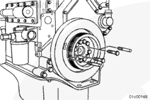
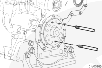
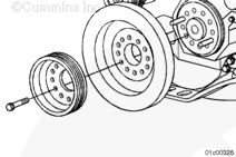
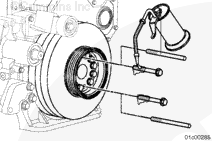
Remove two of the vibration damper(s) and crankshaft pulley retaining capscrews.
Install two guide studs into the holes.
Remove the remaining 10 capscrews.
Remove the pulley and vibration damper(s).
Industrial and Power Generation with Crank-Driven Fan or PTO
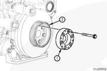
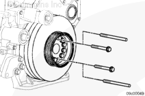
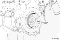
Remove two pulley capscrews.
Install two guide studs into the holes.
CAUTION
Do not use a hammer or a screwdriver to remove the vibration damper. These tools can damage the vibration damper.
Remove the remaining four capscrews.
Remove the pulley (4), vibration damper (3), mounting spacer (2) and second vibration damper (1).
Industrial and Power Generation without Crank-Driven Fan or PTO
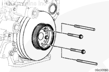
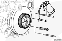
Remove two of the pulley capscrews.
Install two guide studs into the holes.
CAUTION
Do not use a hammer or a screwdriver to remove the vibration damper. These tools can damage the vibration damper.
Remove the remaining 10 capscrews.
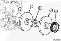
Remove the pulley (4), vibration damper (3), mounting spacer (2), and second vibration damper (1).
Clean and Inspect for Reuse
TOC
All Applications
WARNING
When using solvents, acids, or alkaline materials for cleaning, follow the manufacturer’s recommendations for use. Wear goggles and protective clothing to reduce the possibility of personal injury.
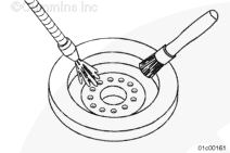
Clean the vibration damper(s) with a solvent cleaner.
Always replace the vibration damper(s) after a crankshaft nose failure. Crankshaft nose breakages are primarily caused by excessive torsional activity.
The vibration dampermust always be measured after a failure involving broken gears in the front gear train.
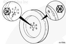
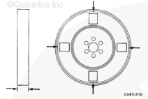
Check the mounting web for cracks.
Check the housing for dents or raised surfaces.
The vibration dampermust be replaced if the mounting web is cracked or the housing has dents or raised surfaces.
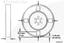
Measure and record the thickness at two points at each of the four locations.
The difference between any two of the eight measurementsmust not exceed 0.25 mm [0.010 in].
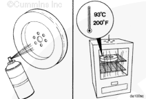
Spray the vibration damper with spot check developer, Type SKD-NF, or equivalent.
Heat the vibration damper in an oven (rolled lip side down) at 93°C [200°F] for two hours.
WARNING
Wear protective gloves when handling parts that have been heated to reduce the possibility of personal injury.
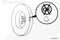
Remove the vibration damper from the oven and check for fluid leakage.
If there is leakage, replace the vibration damper.
Install
TOC
Automotive Applications
Make sure the mounting surfaces of the crankshaft nose, vibration damper, and the pulley are clean, dry, and free from burrs.
Install two guide studs into the crankshaft nose.
Align the dowel pin in the crankshaft wit the dowel hole in the vibration damper.
Install the vibration damper, pulley, and clamping plate onto the guide plate.
Use clean 15W-40 oil to lubricate the capscrew threads.
Install 10 capscrews.
Remove the two guide studs and install the remaining capscrews.
Tighten the capscrews in a star pattern.
Torque Value: 175 n.m [130 ft-lb]
Industrial and Power Generation with Crank-Driven Fan or PTO
Make sure the mounting surfaces of the crankshaft nose, vibration dampers, mounting spacer, and pulley are clean, dry, and free from burrs.
Install two guide studs into the crankshaft nose.
Lubricate the capscrew threads with clean 15W-40 oil.
Install four capscrews.
Remove the two guide studs and install the remaining two capscrews.
Tighten the six capscrews in a star pattern.
Torque Value: 175 n.m [130 ft-lb]
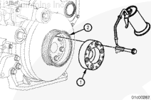
Install the crankshaft adapter (1).
Make sure the crank shaft adapter sets flush against the pulley (2).
Lubricate the capscrew threads with clean 15W-40 oil.
Install the six capscrews and tighten in a star pattern.
Torque Value: 175 n.m [130 ft-lb]
Industrial and Power Generation without Crank-Driven Fan or PTO
Make sure the mounting surfaces of the crankshaft nose, vibration dampers, mounting spacer, and pulley are clean, dry, and free from burrs.
Install two guide studs into the crankshaft nose.
Lubricate the capscrew threads with clean 15W-40 oil.
Install 10 capscrews.
Remove the two guide studs and install the two remaining capscrews.
Tighten the 12 capscrews in a star pattern.
Torque Value: 175 n.m [130 ft-lb]
Eccentricity Check
TOC
All Applications
Clean the outside surface of the vibration damper.
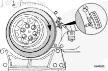
To measure the vibration damper eccentricity (out of round), install a dial indicator onto the gear cover as indicated.
Rotate the crankshaft with the accessory driveshaft one complete revolution (360 degrees), and record the total indicator movement.
Vibration Damper Eccentricity
mm
in
0.28
MAX
0.011
If the vibration damper isnot within specifications, itmust be replaced.
Wobble Check
TOC
All Applications
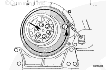
To measure wobble (face alignment), install a dial indicator as shown.
Push the crankshaft to the front or rear of the engine and set the indicator to “0” (zero).
Rotate the crankshaft one complete revolution (360 degrees) while maintaining the position of the crankshaft, either toward the front or rear of the engine.
Record the total indicator movement.
Vibration Damper Wobble Measurement
mm
in
0.28
MAX
0.011
If the vibration damper isnot within specifications, itmust be replaced.
Finishing Steps
TOC
Automotive Applications
Industrial and Power Generation with Crank-Driven Fan or PTO
Industrial and Power Generation without Crank-Driven Fan or PTO
Last Modified: 22-Feb-2007
Published by Jack
Hello, I'm Jack, a diesel engine fan and a blogger. I write about how to fix and improve diesel engines, from cars to trucks to generators. I also review the newest models and innovations in the diesel market. If you are interested in learning more about diesel engines, check out my blog and leave your feedback.
View all posts by Jack


 CAUTION
 WARNING


;)
;)
;)
;)
;)
;)
;)
;)
;)
;)
;)
;)
;)
;)
;)
;)
;)
;)
;)
;)
;)
;)
;)
;)
;)
;)
;)
;)
;)
;)
;)
;)
;)
;)
;)
;)
;)
;)
;)
;)