To reduce the possibility of personal injury, reduce the possibility of direct contact of hot oil with your skin.
WARNING
Some state and federal agencies have determined that used engine oil can be carcinogenic and cause reproductive toxicity. Reduce the possibility of inhalation of vapors, ingestion, and prolonged contact with used engine oil. If not reused, dispose of in accordance with local environmental regulations.
WARNING
Do not remove the pressure cap from a hot engine. Wait until the coolant temperature is below 50°C [120°F] before removing the pressure cap. Heated coolant spray or steam can cause personal injury.
WARNING
Coolant is toxic. Keep away from children and pets. If not reused, dispose of in accordance with local environmental regulations.
WARNING
This component weighs 23 kg [50 lb] or more. To reduce the possibility of personal injury, use a hoist or get assistance to lift this component.
Drain the lubricating oil. Refer to Procedure 007-037.
Drain the cooling system. Refer to Procedure 008-018.
Remove the lubricating oil pan. Refer to Procedure 007-025.
Remove the lubricating oil suction tube. Refer to Procedure 007-035.
Remove the block stiffener plate. Refer to Procedure 001-089.
Remove the piston cooling nozzles. Refer to Procedure 001-046.
Remove the connecting rod cap. Refer to Procedure 001-005.
Remove the cylinder head. Refer to Procedure 002-004.
When using solvents, acids, or alkaline materials for cleaning, following the manufacturer’s recommendations for use. Wear goggles and protective clothing to reduce the possibility of personal injury.
WARNING
Some solvents are flammable and toxic. Read the manufacturer’s instructions before using.
CAUTION
Do not use emery cloth or sandpaper to remove carbon from the cylinder liners. Aluminum oxide or silicon particles from emery cloth or sandpaper can cause serious engine damage. Do not use any abrasives in the ring travel area. The cylinder liner can be damaged.
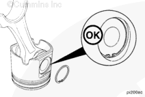
Use a fine fibrous, abrasive pad such as Scotch-Brite™ 7448, Part Number 3823258, or equivalent, and solvent to remove the carbon.
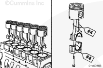
Use both hands to remove the piston and connecting rod assembly.
The piston and connecting rod assemblies must be installed in the same cylinder they were removed from to provide for proper fit of worn mating surfaces if parts are reused.
Use a tag to mark the cylinder number from which each piston and connecting rod assembly was removed.
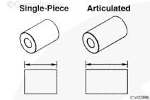
To reduce the possibility of engine damage all pistons within a given engine must be of the same design – all are to be either the articulated design or the single-piece design. Do not mix piston designs in the same engine. Single-piece pistons must have drilled rods and connecting rod bearings. Articulated pistons can use either drilled or non-drilled rods and bearings.
A unique number (not cylinder number) is stamped on the connecting rod and matching connecting rod cap. When the connecting rods and connecting rod cap are installed in the engine, the numbers on the connecting rod and cap must match and be installed on the same side (the exhaust side) of the engine.
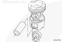
Do not use a hammer to remove the piston pins. The piston can distort, causing it to seize in the liner.
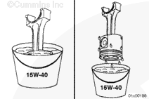
If the piston pin can not be easily removed by hand, place the piston and connecting rod assembly in a container of water. Heat the piston in boiling water for 15 minutes.
Use a blunt tool to push the piston pin from the piston and connecting rod assembly.
When the piston pin is removed from an articulated piston, the skirt will separate from the crown. Use care to prevent damage to the piston.
If they are to be reused, mark the number of the cylinder that the piston, crown, skirt, and pin were removed from on the parts to make sure they are installed in the correct cylinder.
Do not use a hammer to remove the piston pins. The piston can distort, causing it to seize in the liner.
If the piston pin can not be easily removed by hand, place the piston and connecting rod assembly in a container of water. Heat the piston in boiling water for 15 minutes.
Use a blunt tool to push the piston pin from the piston and connecting rod assembly.
The piston and connecting rod assemblies must be installed in the same cylinder they were removed from to provide for proper fit of worn mating surfaces if parts are reused.
Use a tag to mark the cylinder number from which each piston and connecting rod assembly was removed.
Do not use a hammer to install the piston pin. The piston can distort, causing it to seize in the liner.
CAUTION
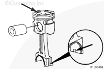
The lock tang on the connecting rod must be in line with the cooling nozzle notch in the piston skirt and on the side opposite the deep valve pocket of the piston crown. Failure to follow this step will cause extensive engine damage.
The piston pin for the articulated piston is longer in length than the pin for single-piece pistons. Do not use articulated piston pins in single-piece pistons. Likewise, do not use single-piece pins in articulated pistons.
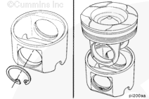
Align the pin bore of the connecting rod with the pin bore of the piston skirt and crown, and install the piston pin.
On articulated pistons, make sure the locking tang on the connecting rod is on the same side as the cooling nozzle notch in the piston skirt and opposite the deep valve pocket on the crown.
Do not use a hammer to install the piston pin. The piston can distort, causing it to seize in the liner.
CAUTION
The lock tang on the connecting rod must be in line with the cooling nozzle notch in the piston skirt and on the side opposite the deep valve pocket of the piston crown. Failure to follow this step will cause extensive engine damage.
Generously coat both single-piece piston pin bores with a heavy weight gear oil, such as 85W-140 EP, when assembling single-piece pistons. Also lubricate the connecting rod bushing. If gear oil is not available, Lubriplate, Part Number 3163086, is permissible. Failure to adequately lubricate the pin joint can result in extensive engine damage, particularly with single-piece pistons.
The single-piece piston requires a drilled connecting rod and a drilled upper connecting rod bearing to lubricate the pin joint. Do not assemble a single-piece piston with a non-drilled connecting rod nor a non-drilled connecting rod bearing. Make certain when assembling a single-piece piston that the lubricating hole in the connecting rod bearing lines up with lubricating hole in the connecting rod.
The piston pin for single-piece pistons is shorter in length than the pin for articulated pistons. Do not use single-piece piston pins in articulated pistons. Likewise, do not use articulated pins in single-piece pistons.
Use a clean, lint-free cloth to clean the connecting rods and bearing shells.
Do not lubricate the backside of the bearing shells. The operating clearance of the bearing will be reduced and the bearing can be damaged during engine operation.
Use the compressor drive or barring device to rotate the crankshaft so the connecting rod journal of the connecting rod being installed is at bottom dead center.
Failure to align the deep valve pocket and the piston skirt cooling nozzle notch correctly will result in extensive engine damage.
Align the piston crown deep valve pocket on the exhaust side of the engine, and the piston skirt cooling nozzle notch to the intake side of the engine.
If the deep valve pocket and the piston skirt cooling nozzle notch are not on opposite sides, the piston and connecting rod assembly are not assembled correctly. Disassemble the piston and connecting rod and assemble correctly.
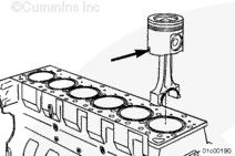
Insert the connecting rod through the cylinder liner until the ring compressor contacts the top of the liner.
Both articulated pistons and single-piece pistons have an arrow on the top of the piston crown, which will point to the front of the engine, when the piston is installed properly.
Do not use a metal drift to push the piston into the cylinder liner. The piston rings or cylinder liner can be damaged.
Hold the ring compressor against the cylinder liner. Push the piston through the ring compressor and into the cylinder liner. Push the piston until the top ring is completely in the cylinder liner.
If the piston does not move freely, remove the piston and inspect for broken or damaged rings.
NOTE: When rebuilding an engine with single-piece pistons that was originally built with articulated pistons, stamp the dataplate with the letters SP. This will alert future repair locations that this engine has been rebuilt with single-piece pistons.
Install the connecting rod cap. Refer to Procedure 001-005.
Install the piston cooling nozzles. Refer to Procedure 001-046.
Install the block stiffener plate. Refer to Procedure 001-089.
Install the lubricating oil suction tube. Refer to Procedure 007-035.
Install the lubricating oil pan. Refer to Procedure 007-025.
Install the cylinder head. Refer to Procedure 002-004.
Prime the lubricating oil system. Refer to Procedure 007-037.
Fill the coolings system with coolant. Refer to Procedure 008-018.
Fill the engine with clean lubricating oil. Refer to Procedure 007-037.
Operate the engine to normal operating temperature and check for leaks.
Hello, I'm Jack, a diesel engine fan and a blogger. I write about how to fix and improve diesel engines, from cars to trucks to generators. I also review the newest models and innovations in the diesel market. If you are interested in learning more about diesel engines, check out my blog and leave your feedback.
View all posts by Jack
 WARNING


 CAUTION


;)
;)
;)
;)
;)
;)
;)
;)
;)
;)
;)
;)
;)
;)
;)
;)
;)
;)
;)
;)
;)
;)
;)
;)
;)
;)
;)
;)
;)
;)
;)
;)
;)
;)
;)
;)
;)
;)
;)
;)
;)
;)
;)
;)
;)
;)
;)
;)
;)
;)
;)
;)
;)
;)
;)
;)
;)
;)
;)
;)
;)
;)