|
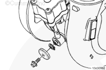
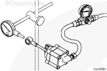
Attach a dial indicator as shown, so the shaft is in line with the actuator rod.
Set the dial indicator to zero, with no air pressure applied to the actuator.
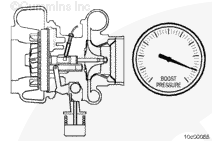
Connect clean, regulated air pressure and a pressure gauge to the actuator.
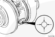
Apply a minimum of 414 kPa [60 psi] to make sure the actuator is functioning properly.
The rod
must move without any sticking.
| Actuator Movement Range |
| mm |
|
in |
| 12 |
MIN |
0.472 |
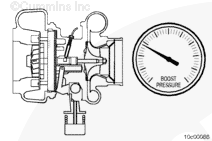
Air
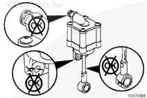
must not be heard leaking through a functional actuator.
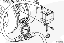
Spray soapy water on the actuator housing to check for air leaks.
Replace the actuator housing if leaks are found.
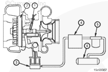
Replace the actuator if no movement of the actuator rod is detected, the actuator is sticking, or an air leak is found.
This test can be performed with the actuator removed or installed on the turbocharger.
|
 CAUTION

 WARNING


;)
;)
;)
;)
;)
;)
;)
;)
;)
;)
;)
;)
;)
;)
;)
;)
;)
;)