Incorrect or insufficient break-in of the piston rings will lead to early oil consumption or high blowby complaints. Adherence to these run-in guidelines will allow the full durability of new pistons, liners, and rings to be realized.
This section outlines engine testing and engine run-in recommendations for M series engines. All engines must be run-in after a rebuild or a repair involving the replacement of one or more piston ring sets, cylinder liners, or cylinder kits.
Before running the engine, make sure the engine is filled with the proper coolant. Also, be sure the lubricating oil system is filled and primed.
The majority of heavy-duty diesel applications will provide sufficient run-in under normally loaded operations. However, light-load/high-rpm operation must be avoided during the run-in period. The following in-service run-in guidelines are recommended for M series engines, after a repair involving replacement of one or more of the piston ring sets, cylinder liners, or cylinder kits, where engine or an engine dynamometer and/or chassis dynamometer run-in can not be performed.
Engine Dynamometer Run-In:
This is the preferred method of run-in for engines that have been rebuilt out of chassis. It is neither practical nor recommended that an engine be removed from the application to conduct the run-in after a rebuild or cylinder repair has been performed in-chassis. It is neither required nor recommended that an engine, which has been run-in and tested on a dynamometer, be run-in again after having been installed in the vehicle.
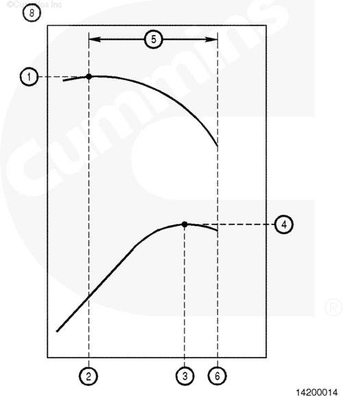
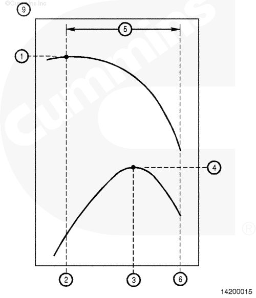
Peak Torque (N•m [ft-lb]) (1) – Maximum torque that the engine will produce. This is listed on the engine dataplate.
Peak Torque rpm (2) – Engine speed at which peak torque is generated. This is listed on the engine dataplate.
Maximum hp rpm (3) – Engine speed at which maximum power is developed. This is listed with advertised horsepower on the engine dataplate.
Advertised Horsepower (hp) (4) – Maximum power that the engine will develop. This is provided on the engine dataplate with its corresponding engine speed.
Operating Range (5) – The engine’s operating range from peak torque up to the engine’s governed speed.
Full-Load Governed Speed (6) – Defined as the upper end of the engine’s full-load operating range. This is listed on the engine dataplate.
No-Load Governed Speed – ( not shown) Maximum unloaded engine speed. This value is listed on the engine data sheet and in the FPEPS publications.
Line Haul Rating (8) – An engine that has a line haul rating has a narrow operating range (rpm). A line haul rating is typically used for on-highway applications. These engines are used with larger (more gears, 13 speed, and so forth) transmissions with close ratio splits between gear shifts.
Vocational Rating (9) – A vocational-rated engine has a wider operating range (rpm). This rating is typically used for on and off, or off-highway applications. These engines are used with smaller (fewer gears, 9 speeds, and so forth) transmissions with large ratio splits between gear shifts.
The amount of time specified for the following engine run-in phases are minimums.
The engine can be operated for longer periods of time at each operating range or phase, with the exception of engine idling, which must be kept to 5 minutes or less.
Do not operate the engine at idle speed longer than specified during engine run-in. Excessive carbon formation will occur and cause damage to the engine.
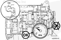
Start the engine and idle for initial check.
Avoid long idle periods. Operate the engine at low idle only long enough (5 minutes maximum) to check for correct oil pressure and any fuel, oil, water, or air leaks.
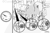
While the engine is idling, listen for unusual noises; watch for coolant, fuel, and lubricating oil leaks; and check for correct engine operation in general.
Repair all leaks and/or component problems before continuing the engine run-in.
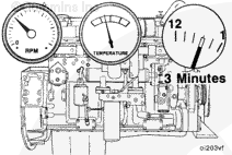
Do not shut off the engine immediately after the run-in is completed. Allow the engine to cool by operating at low idle for a minimum of 3 minutes to avoid internal component damage.
Accurate fuel flow measurement is important for evaluation of engine performance and troubleshooting on an engine or chassis dynamometer. The only way accurate fuel flow measurement can be obtained is through proper use of the available equipment. Below is a description of the fuel measuring device, available from Cummins Inc., along with installation and operation recommendations. The fuel measuring device, Part Number 3376375, can be used with either a chassis or engine dynamometer.
Installation:
When installing the fuel measuring device, it is important to reduce the amount of air that can be introduced into the system when the device is not in use. Therefore, the plumbing used must include nonrestrictive shutoff valves, such as ballcock valves, to contain fuel in the device after each use. Additional installation considerations are:
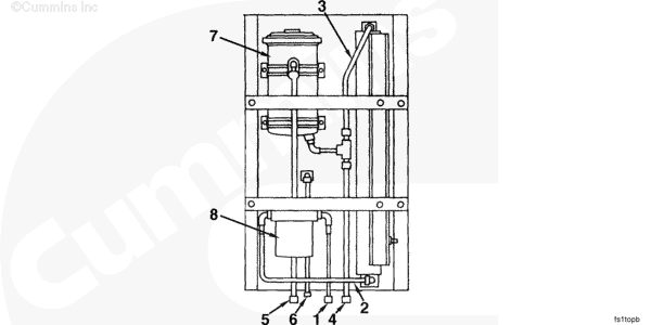
The fuel measuring device, Part Number 3376375, must be mounted vertically to maintain accuracy and proper operation.
A separate fuel supply for use on the dynamometer is recommended. All fuel used in the measuring device must be clean for consistent operation.
Care must be taken to reduce fuel line restriction to and from the engine. Minimum recommended hose sizes are Number 10 for the engine fuel inlet and Number 8 for the engine fuel drain. The length of either hose must not exceed 4.6 m [15 ft].
For accurate fuel consumption or flow measurement while testing on a chassis dynamometer, it is recommended to use a fuel cooler to maintain inlet temperature to the fuel gear pump at 49°C [120°F] or below.
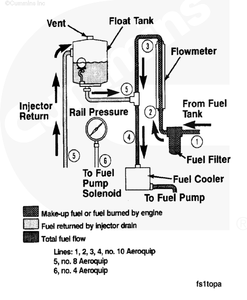
The fuel measuring device recirculates return fuel to the engine fuel inlet by routing the return fuel to the top side of the float tank. The fuel is de-aerated as it passes through the baffling in the float tank. A ball float valve at the bottom of the float tank maintains an adequate volume in the tank for de-aeration. The fuel is then returned to the engine fuel inlet. Refer to the sketch for fuel line connection points on the fuel measuring device.
Fuel supply from tank
Fuel flow to fuel meter
Fuel flow from fuel meter
Fuel flow to fuel cooler
Injector return fuel
Fuel rail pressure.
The fuel supply tank must be below the level of the fuel measuring device to prevent overflow of the float tank. If an overhead fuel supply tank is used, a float-controlled reservoir must be installed between the fuel supply tank and the fuel measuring device, and below the level of the device.
The fuel measuring device is installed in series between the fuel supply tank and the engine fuel inlet. The quantity of fuel being drawn through the flow meter is know as “makeup” fuel, or the amount of fuel being burned by the engine.
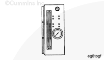
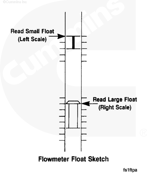
The flow meter is graduated to read fuel flow in pounds per hour. The flow meter contains two floats with respective scales on either side of the flow meter. The small float is used to measure lower flows and must be read on the left scale, as shown. The larger float is for measuring higher flows and must be read on the right scale.
To obtain an accurate fuel rate measurement, the flow meter reading must be corrected, based on the fuel temperature. There is a fuel temperature gauge on the front panel of the fuel measuring device. The gauge is graduated in percent of error by which the reading requires correction. An example is: The fuel of an engine reads 125 lbs/hr on the flow meter, and the temperature gauge reads +2 percent; the corrected fuel flow rate will be 125 plus 2 percent, or 127.5 lbs/hr.
Hello, I'm Jack, a diesel engine fan and a blogger. I write about how to fix and improve diesel engines, from cars to trucks to generators. I also review the newest models and innovations in the diesel market. If you are interested in learning more about diesel engines, check out my blog and leave your feedback.
View all posts by Jack
 CAUTION


;)
;)
;)
;)
;)
;)
;)
;)
;)
;)
;)
;)
;)
;)
;)
;)
;)
;)
;)
;)
;)
;)
;)
;)