Do not pull or pry on the fan blades to rotate the crankshaft. Doing so can damage the fan blades. Damaged fans blades can cause premature fan failures, which can result in serious personal injury or property damage.
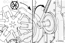
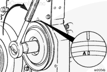
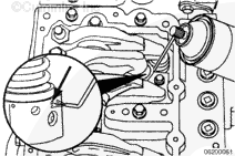
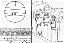
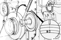
The valve set marks are located on the accessory drive pulley. The marks align with a pointer on the gear housing.
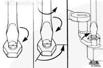
Use the accessory driveshaft to rotate the crankshaft.
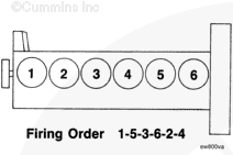
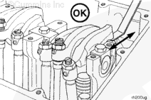
When the “A” mark is aligned with the pointer, the intake and exhaust valves for cylinder number 1 must be closed. The injector plunger for cylinder number 1 must be at the bottom of its stroke. If these conditions are not correct, cylinder number 6 must be ready to check. Check the injector and valves on the cylinde, make sure both the intake and exhaust valve rocker levers can be rattled by hand or the push tubes can be freely rotated.
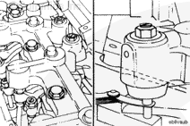
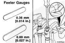
Use a set of feeler gauges to measure the amount of clearance (lash) between the crosshead and the rocker lever nose.
Measure and record the intake and exhaust valve lash. If the valve lash is not within the specifications listed below, the valve must be adjusted. See the Adjust step in this procedure.
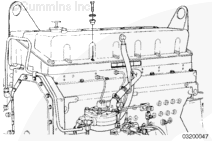
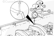
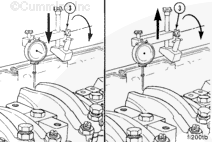
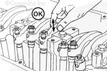
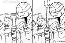
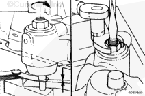
Install the dial indicator and the support from injector travel measurement kit so the extension for the dial indicator is on top of the injector rocker lever, directly over the socket on the cylinder being checked.
Securely tighten the thumbscrew (1) and hold down the capscrews (2 and 3).
All adjusting screws must be tight for an accurate measurement.
The injector plunger is under spring-tension. Do not allow the tool to slip. Serious personal injury can result.
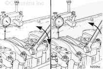
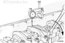
Actuate the injector plunger three or four times to remove the fuel from the injector assembly. Allow the lever to return slowly to prevent damage to the dial indicator.
Actuate the lever again. Set the dial indicator at zero while holding the injector plunger to the bottom of its travel.
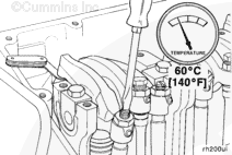
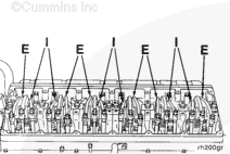
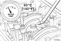
Valves, injectors, and engine brakes must be correctly adjusted for the engine to operate efficiently. Valve, injector, and engine brake adjustment must be performed using the values listed in this section. The accompanying table gives the adjustment specifications.
If the valves and injectors have been adjusted during troubleshooting or before this scheduled interval, adjustment is not required at this time.
Valve, Injector, and Engine Brake Adjustment Specifications
When using solvents, acids, or alkaline materials for cleaning, follow the manufacturer’s recommendations for use.
WARNING
Use skin and eye protection when handling caustic solutions to reduce the possibility of personal injury.
WARNING
Some solvents are flammable and toxic. Read the manufacturer’s instructions before using.
Clean the timing plunger to remove the varnish from the top edge.
Apply a non-chlorinated carburetor cleaner (Pyroil®, or equivalent). Use a narrow bore orifice or extension tube of 2 mm [0.079 in] maximum outside diameter (O.D.), into the injector weep hole.
If the entire overhead is to be reset, every injector is to be sprayed at this time.
Do not straighten a bent fan blade or continue to use a damaged fan. A bent or damaged fan blade can fail during operation and cause personal injury or property damage.
The valve set marks are located on the accessory drive pulley. The marks align with a pointer on the gear cover.
Use the accessory driveshaft to rotate the crankshaft.
The adjustment can begin on any valve set mark. In the following example, the adjustment will begin on the “A” valve set mark with cylinder number 1 valves closed and ready for adjustment.
Rotate the accessory drive clockwise until the “A” valve set mark on the accessory drive pulley is aligned with the pointer on the gear cover.
When the “A” mark is aligned with the pointer, the intake and exhaust valves for cylinder Number 1 must be closed. If these conditions are not correct, cylinder number 6 injector and valves must be ready to set. Set the injector and valves on the cylinder so that both the intake and exhaust valve rocker lever arms are loose and can be moved from side-to-side.
Both valves are closed when both rocker levers are loose and can be moved from side-to-side.
Use a screwdriver or a box end wrench, if equipped with engine brakes) to adjust the screw. Bottom the injector plunger three or four times to remove the fuel.
Turn the adjusting screw in until it just bottoms the plunger.
NOTE: Do not use excessive force when bottoming the plunger.
Back out the adjusting screw two flats, 120 degrees.
Hold the adjusting screw, and tighten the locknut.
With the “A” valve set mark aligned with the pointer on the gear cover and both valves closed on the cylinder to be adjusted, loosen the adjusting screw locknuts on the intake and exhaust valves.
Two different methods for establishing valve lash clearance are described below. Either method can be used; however, the torque wrench method has proven to be the most consistent. It eliminates the need to feel the drag on the feeler gauge.
Torque Wrench Method: Insert the correct feeler gauge. Use an inch-pound torque wrench, Part Number 3376592, normally used to set preload on top-stop injectors, and tighten the adjusting screw.
Torque Value: 0.7 n.m [6 in-lb]
Touch Method: Tighten the adjusting screw until a slight drag is felt on the feeler gauge.
After tightening the locknut to the correct torque value, check to make sure the feeler gauge will slide backward and forward between the crosshead and the rocker lever with only a slight drag.
If using the touch method, attempt to insert a feeler gauge that is 0.03 mm [0.001 in] thicker between the crosshead and the rocker lever pad. The valve lash is not correct when a thicker feeler gauge will fit.
After adjusting the injector, valves, and engine brakes (if equipped) on the appropriate cylinder, rotate the accessory drive pulley, and align the next valve set mark with the pointer on the gear cover.
If damage resulted in coolant, oil, excessive fuel or excessive black smoke entering the exhaust system, the aftertreatment system must be inspected. Refer to Procedure 014-013 in Section 14.
Hello, I'm Jack, a diesel engine fan and a blogger. I write about how to fix and improve diesel engines, from cars to trucks to generators. I also review the newest models and innovations in the diesel market. If you are interested in learning more about diesel engines, check out my blog and leave your feedback.
View all posts by Jack


 WARNING


;)
;)
;)
;)
;)
;)
;)
;)
;)
;)
;)
;)
;)
;)
;)
;)
;)
;)
;)
;)
;)
;)
;)
;)
;)
;)
;)
;)
;)
;)
;)
;)
;)
;)
;)
;)
;)
;)
;)
;)
;)
;)
;)
;)
;)
;)
;)
;)
;)
;)
;)
;)