NOTE: This action applies only to engines built with cast-iron supports.
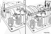
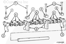
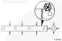
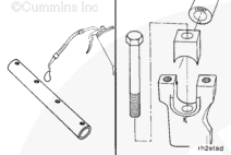
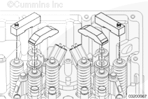
Install a piece of 1/4-inch key stock 457 mm [18 in] long on top of the four front rocker lever assembly supports. Use four M10 – 1.50 x 25 flange head capscrews to secure the bar stock to the supports.
The capscrews on the two end supports fasten to the engine brake mounting holes on one side of the bar stock. The capscrews on the two center supports fasten to the engine brake mounting holes on the opposite side of the bar stock.
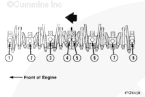
Loosen, but do not remove, the eight rocker shaft capscrews. The capscrews hold the rocker lever assemblies together.
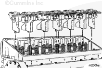
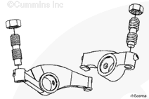
NOTE: Engines with cast-iron supports: Grasp the bar stock and lift the front rocker lever assembly from the engine. Do not lift the assemblies by grasping the rocker levers and shaft. The shaft and levers can lift out of the supports allowing the levers to slide off the shaft.
NOTE: Engines with aluminum supports: Grasp the assembly by the rocker levers and shaft and lift them from the engine. The shafts can not lift out of the supports.
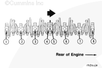
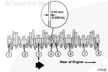
Repeat the process to remove the rear rocker lever assembly.
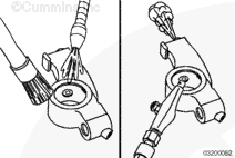
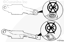
Inspect the rocker lever shafts for pitting, scoring, or other damage.
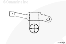
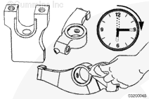
Measure each rocker lever shaft outside diameter.
Rocker Lever Shaft Outside Diameter
mm
in
34.837
MIN
1.3715
34.864
MAX
1.3726
If worn or damaged parts are found, or the rocker lever bushings or shafts are not within the specifications given, the rocker lever assemblies must be rebuilt.
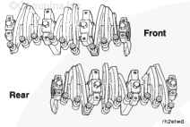
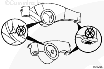
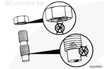
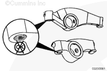
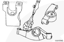
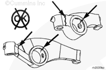
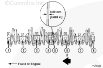
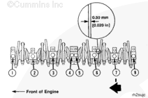
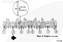
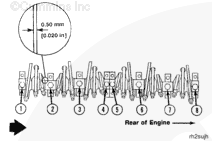
Make sure the rocker lever shafts are installed with the arrow on the end of the shafts pointing DOWN. When the arrow points up, cross-drilling to the rocker levers are orientated differently, which has an adverse affect to rocker lever oiling.
The rocker lever shafts are labeled front (or “F”) and rear on the end of the shafts (1). The arrows on the shafts (2) must be pointed downward to maintain an oil flow to the rocker levers.
The rocker lever assemblies must be installed in the engine so they are in the same position as they were removed from.
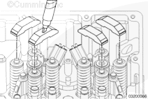
Install the assemblies on the engine.
NOTE: Hand-tighten the mounting capscrews. The rocker lever side clearance must be adjusted before the capscrews are tightened to their final torque value.
Hello, I'm Jack, a diesel engine fan and a blogger. I write about how to fix and improve diesel engines, from cars to trucks to generators. I also review the newest models and innovations in the diesel market. If you are interested in learning more about diesel engines, check out my blog and leave your feedback.
View all posts by Jack


 WARNING

 CAUTION
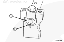


;)
;)
;)
;)
;)
;)
;)
;)
;)
;)
;)
;)
;)
;)
;)
;)
;)
;)
;)
;)
;)
;)
;)
;)
;)
;)
;)
;)
;)
;)
;)
;)
;)
;)
;)
;)
;)
;)
;)
;)
;)
;)
;)
;)
;)
;)
;)
;)
;)
;)
;)
;)
;)
;)
;)
;)
;)
;)
;)
;)
;)
;)