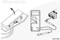
Slowly depress the accelerator pedal, and measure the resistance.
The multimeter must show an open circuit (100k ohms or more) when the pedal is depressed to the OFF-IDLE zone.
If the resistance values are not within specifications, there is a problem in the OEM harness, provided the idle validation switch has been previously checked.
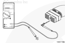
Touch the test lead attached to the multimeter probe to the active off-idle signal pin. Slowly depress the accelerator pedal, and measure the resistance.
The multimeter must show 10 ohms or less for separate sensor/switch pedals and 125 ohms or less for integrated sensor/switch pedals when the pedal is depressed to the OFF-IDLE zone.
Let the accelerator pedal return to the idle (up) position, and measure the resistance.
The multimeter must show an open circuit (100k ohms or more) when in the ON-IDLE zone.
If the resistance values are not within the specifications, there is a problem in the OEM harness, provided the idle validation switch has been previously checked. Check for short circuits to ground, supply, and from pin to pin.
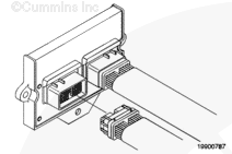
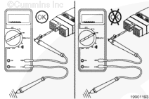
NOTE: When checking the OEM harness, examine the bulkhead connector and other connectors in the circuit for corrosion or damage to the idle validation switch terminals.
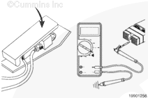
Disconnect engine harness ECM connector 2 from the ECM.
Measure the resistance from the active idle signal pin in the ECM connector to engine block ground.
The multimeter must show an open circuit (100k ohms or more).
Measure the resistance from the active off-idle signal pin in the ECM connector to engine block ground.
The multimeter must show an open circuit (100k ohms or more).
If the multimeter does not show an open circuit, repair or replace the engine harness. Refer to Procedure 019-204 to repair the harness, and Procedure 019-043 to replace the harness.
Disconnect both engine harness ECM connectors from the ECM.
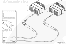
Measure the resistance from the active idle pin in engine harness ECM connector 2 to all other pins in the connector. Measure the resistance from the active idle pin in engine harness ECM connector 2 to all pins in engine harness ECM connector 1.
The multimeter must show an open circuit (100k ohms or more). If a closed circuit is measured between any pins, there is a short circuit between the applicable pins. Repair or replace the engine harness. Refer to Procedure 019-204 to repair the harness, and Procedure 019-043 to replace the harness. to replace the harness.
Measure the resistance from the active off-idle signal pin in engine harness ECM connector 2 to all other pins in the connector. Measure the resistance from the active off-idle pin in engine harness ECM connector 2 to all pins in engine harness ECM connector 1.
The multimeter must show an open circuit (100k ohms or more). If a closed circuit is measured between any pins, there is a short circuit between the applicable pins. Repair or replace the engine harness. Refer to Procedure 019-204 to repair the harness, and Procedure 019-043 to replace the harness. to replace the harness.
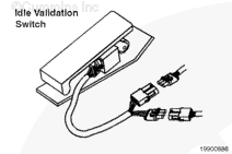
To isolate the idle validation switch circuit, turn all cab panel switches to the OFF or neutral position.
Disconnect the idle validation switch from the accelerator assembly. Disconnect the engine harness ECM connector 2 from the ECM. Set the multimeter to measure VDC. Turn the keyswitch to the ON position.
Measure the voltage, touching the positive (+) multimeter probe to the active idle signal pin in the ECM connector and the negative (-) probe to engine block ground. The multimeter must show a measurement of 1.5 VDC or more.
Measure the voltage from the active off-idle signal pin in the ECM connector to engine block ground. The multimeter must show a measurement of 1.5 VDC or more. If the voltage is not to specification in either step, repair or replace the engine harness. Refer to Procedure 019-204 to repair the harness, and Procedure 019-043 to replace the harness.
Hello, I'm Jack, a diesel engine fan and a blogger. I write about how to fix and improve diesel engines, from cars to trucks to generators. I also review the newest models and innovations in the diesel market. If you are interested in learning more about diesel engines, check out my blog and leave your feedback.
View all posts by Jack


;)
;)
;)
;)
;)
;)
;)
;)
;)
;)
;)
;)
;)
;)