Electronic Control System Gas Plus Engines – 019-439   Sensor Supply Voltage Converter

Table of Contents

Initial Check
Remove
Install

Initial Check

TOC

Disconnect the Sensor Supply Voltage Converter from the Gas Mass Flow Sensor.

SMALL | MEDIUM | LARGE


Insert a 40 ohm 10 watt resistor across Gas Mas Flow Sensor connector supply and return pins.

Turn the keyswitch to the on position and measure the voltage across the resistor.

The output voltage must be 15.23 VDC ± 0.5 VDC. If the voltage is outside of this range, replace the Sensor Supply Voltage Converter.

SMALL | MEDIUM | LARGE
   

Remove

TOC

Disconnect the Sensor Supply Voltage Converter from the engine harness.

Slide the locking tab sideways and push down on the button toward the rear of the connector and disconnect from the connector.

SMALL | MEDIUM | LARGE


Disconnect the Sensor Supply Voltage Converter from the Gas Mass Flow Sensor.

SMALL | MEDIUM | LARGE


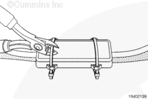
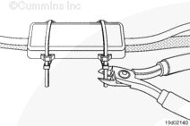
Cut the plastic ties holding the Sensor Supply Voltage Converter to the main harness. Use caution when cutting the ties to avoid damaging the main engine harness.

SMALL | MEDIUM | LARGE
   

Install

TOC

Connect the Sensor Supply Voltage Converter to the main engine harness with plastic ties. To reduce the possibility of damage to the main harness, do not over tighten the wire ties.

Trim the wire ties after tightening.

SMALL | MEDIUM | LARGE


Connect the Sensor Supply Voltage Converter to the Gas Mass Flow Sensor.

SMALL | MEDIUM | LARGE


Connect the Sensor Supply Voltage Converter to the engine harness. Slide the locking tab sideways to lock the connector.

SMALL | MEDIUM | LARGE
Last Modified:  13-Jul-2004