The fuel pump, high-pressure fuel lines, and fuel rail contain very high-pressure fuel. Do not loosen any fittings while the engine is running. Wait at least 10 minutes after shutting down the engine before loosening any fittings in the high-pressure fuel system to allow pressure to decrease to a lower level.
CAUTION
Use caution when disconnecting or removing fuel lines, replacing filters and priming the fuel system that fuel is not spilled or drained into the bilge area. Do not drop or throw filter elements into the bilge area. The fuel and fuel filters must be discarded in accordance with local environmental regulations.
CAUTION
Installation of the banjo flow adapter at any place other than the fuel drain manifold can cause damage to high pressure fuel system components.
Return fuel is routed from the injectors, the fuel rail pressure relief valve, and the fuel pump head through three different drain lines.
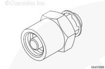
Measurement of fuel injector leakage requires the use of a fuel return hose, Part Number 3164618.
The tool is used to isolate the leakage from just the injectors, so it can be measured with a graduated cylinder.
Depending on the circumstance, diesel fuel is flammable. When inspecting or performing service or repairs on the fuel system, to reduce the possibility of fire and resulting severe personal injury, death or property damage, never smoke or allow sparks or flames (such as pilot lights, electrical switches, or welding equipment) in the work area.
CAUTION
Use caution when disconnecting or removing fuel lines, replacing filters and priming the fuel system that fuel is not spilled or drained into the bilge area. Do not drop or throw filter elements into the bilge area. The fuel and fuel filters must be discarded in accordance with local environmental regulations.
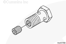
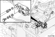
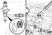
Remove the M12 banjo bolt that connects the fuel injector drain line to the fuel drain manifold.
Install the M12 fuel return hose, Part Number 3164618, at the fuel drain manifold.
Route the fuel return hose into a collection device.
Obtain a graduated cylinder that is marked in cubic centimeters; example: graduated beaker, Part Number 3823705, or equivalent. A kitchen style measurement cup that is marked in cubic centimeters (cc’s) also works well.
Fuel is at high pressure during this test. After connecting the test fitting, close the engine cover and stand clear of high-pressure fuel lines.
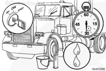
If the engine will start, the following steps will determine if the injector drain flow is excessive.
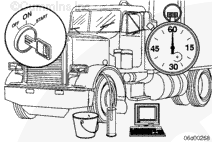
While the engine is operating at idle, use INSITE™ electronic service tool High Pressure Leak Test to create high fuel rail pressure. INSITE™ electronic service tool will command 1500 BAR [21,756 psi] fuel rail pressure while the engine is at idle during this test.
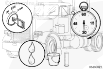
Record the amount of time it takes for 300 cc [10.1 oz] of fuel to flow from the injector drain line when performing the INSITE™ electronic service tool High Pressure Leak Test.
Leakage Specification With Engine Running
Maximum Leakage During 45 Seconds
300 cc [10.1 oz]
If 300 cc [10.1 oz] of fuel leaks from the injectors in less than 45 seconds, there is at least one loose or damaged high pressure fuel connector and/or injector.
NOTE: Fuel temperature and fuel type will influence this measurement. For example; as the engine is warmed up and the injectors become hot, the leakage rate will increase. Also, low viscosity fuels, such as kerosene, will cause the leakage rate to increase. The above specification is correct for on-highway diesel fuels where fuel inlet temperature is less than 49°C [120°F].
After recording the fuel leakage rate, stop INSITE™ electronic service tool High Pressure Leak Test and turn the keyswitch to OFF.
If injector drain flow is excessive, it will be necessary to isolate the injector(s) or fuel connector(s) that are damaged or worn.
A loose fuel connector retaining nut results in a poor seal at the interface between the fuel connector and the injector. This loose condition will result in a leak of high-pressure fuel to the injector drain.
Do not install the isolation tool at the high pressure pump outlet fitting. Severe engine damage will result. This tool must only be installed at the fuel rail for the purpose of isolating the high-pressure fuel supply from individual injectors.
CAUTION
Make certain the keyswitch is in the OFF position (engine not running) when loosening or tightening high-pressure fuel lines.
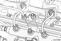
Use leak test isolation tool, Part Number 3164325, to isolate excessive fuel drainage from injectors or fuel connectors.
Isolate the injector and fuel connector for each cylinder by installing the isolation tool at the fuel rail in place of the high-pressure fuel line that supplies the fuel connector.
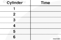
Record the amount of time it takes for 300 cc [10.1 oz] of fuel to flow from the injector drain line while the engine is running. Use INSITE™ electronic service tool High Pressure Leak Test. Do this up to six (6) times, once while each line is isolated.
If isolating a single injector and high-pressure fuel connector causes the leakage time to increase significantly compared to the rest of the set, that injector and fuel connector must be inspected.
Inspect the suspect fuel connector. Refer to Procedure 006-052 in Section 6. If the fuel connector is not damaged, replace both the injector and the fuel connector.
Batteries can emit explosive gases. To reduce the possibility of personal injury, always ventilate the compartment before servicing the batteries. To reduce the possibility of arcing, remove the negative (-) battery cable first and attach the negative (-) battery cable last.
CAUTION
Use caution when disconnecting or removing fuel lines, replacing filters and priming the fuel system that fuel is not spilled or drained into the bilge area. Do not drop or throw filter elements into the bilge area. The fuel and fuel filters must be discarded in accordance with local environmental regulations.
CAUTION
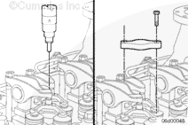
Attempting to remove the injector without first removing the fuel connector will cause damage to the injector body and/or fuel connector.
While testing the injectors, keep hands and body parts away from the injector nozzle. Fuel coming from the injector is under extreme pressure and can cause serious injury by penetrating the skin.
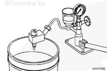
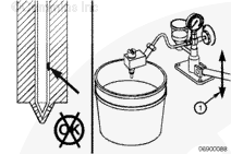
Install the injectors on an injector test stand. Open the bypass valve for the pressure gauge, so the spray pattern can be checked.
Use injector test fixture, Part Number 3162269, with the injector nozzle test, Part Number 3376946.
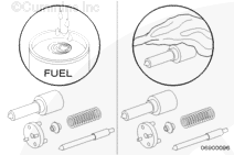
Operate the test stand lever quickly several times to check the spray pattern of the injectors. Verify that the correct number of plumes are present for the number of holes in the injector. Also pay close attention to the size and shape of each plume. If possible, compare the spray pattern to that of a new injector with the same assembly number.
NOTE: The injector spray pattern is an excellent indicator of the nozzle hole condition. Check each plume carefully. It is possible that only a single hole has been damaged, resulting in degraded engine performance.
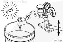
Close the bypass valve for the pressure gauge and operate the test stand lever to check the nozzle opening pressure. There must be a good crisp “pop” when the nozzle opens and the pressure must be within the specification for the assembly number.
The injector will pop between 275 bar [3,989 psi] and 300 bar [4,351 psi].
If the nozzle opening pressure is excessively low and/or the nozzle sprays excessive fuel, the injector needle can be sticking. The needle can be stuck due to poor lubrication or debris.
Sometimes it is possible to unstick an injector needle by using the injector test stand. Open the bypass valve for the pressure gauge and operate the test stand lever rapidly for 10 to 20 strokes.
Recheck the nozzle opening pressure and spray pattern to see if the injector has returned to normal operation.
If the injector is still out of specification, replace the injector.
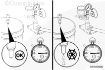
Check the injector for drip and/or excessive leak down. Close the bypass valve for the pressure gauge and build pressure to within 10 bars [145 psi]of the opening pressure of the nozzle.
When using solvents, acids, or alkaline materials for cleaning, follow the manufacturer’s recommendations for use. Wear goggles and protective clothing to avoid personal injury.
WARNING
Some solvents are flammable and toxic. Read the manufacturer’s instructions before using.
CAUTION
Do not use a steel wire brush or glass beading to clean the injectors. This will damage the nozzle holes and cause performance problems.
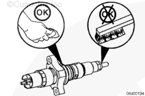
Clean the injector tip and body with safety solvent and a soft, clean, cloth.
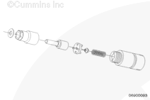
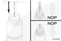
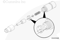
Install shims, as necessary, to modify the nozzle opening pressure. More shims raise the nozzle opening pressure, less shims lower the nozzle opening pressure.
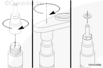
Install the retaining nut finger tight. Place the injector in the injector clamp and tighten the retaining nut. Install the sealing washer and body o-ring.
NOTE: Make sure to tighten the hold-down clamp capscrews evenly. Check to make sure the gap between the hold-down clamp and the injector is equally spaced around the injector body.
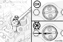
Do not overtighten the injector harness. The injector terminals will be damaged if excessive over-torqued.
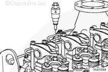
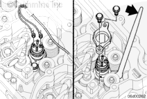
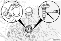
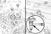
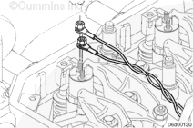
Install the injector wiring harness to the injector.
Torque Value: 1.25 n.m [11 in-lb]
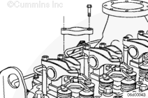
NOTE: Orient the injector wires so they will not interfere with a rocker lever or engine brake housing. If the rocker lever is able to come into contact with the injector harness, it will rub through the wire insulation and cause injector circuit fault codes.
NOTE: Polarity of the wiring is not significant. The signal and return wires can be connected to either injector terminal.
Hello, I'm Jack, a diesel engine fan and a blogger. I write about how to fix and improve diesel engines, from cars to trucks to generators. I also review the newest models and innovations in the diesel market. If you are interested in learning more about diesel engines, check out my blog and leave your feedback.
View all posts by Jack
 WARNING
  CAUTION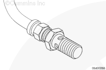











;)
;)
;)
;)
;)
;)
;)
;)
;)
;)
;)
;)
;)
;)
;)
;)
;)
;)
;)
;)
;)
;)
;)
;)
;)
;)
;)
;)
;)
;)
;)
;)
;)
;)
;)
;)
;)
;)
;)
;)
;)
;)
;)
;)
;)
;)
;)
;)
;)
;)
;)
;)
;)
;)
;)
;)
;)
;)
;)
;)
;)
;)