Batteries can emit explosive gases. To reduce the possibility of personal injury, always ventilate the compartment before servicing the batteries. To reduce the possibility of arcing, remove the negative (-) battery cable first and attach the negative (-) battery cable last.
CAUTION
Use caution when draining coolant that coolant is not spilled or drained into the bilge area. Do not pump the coolant overboard. If the coolant is not reused, it must be discarded in accordance with local environmental regulations.
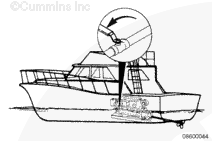
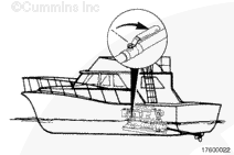
NOTE: This procedure applies to marine engines only.
Removing the sea water supply line for the shaft log seal will allow sea water to leak into the vessel, if the line is not plugged. To reduce the possibility of damage, be sure to plug the supply line and prevent sea water from leaking into the vessel.
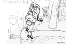
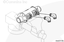
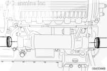
Remove the aftercooler sea water discharge hose from the gear cooler.
Remove the marine gear cooler sea water discharge hose form the gear cooler.
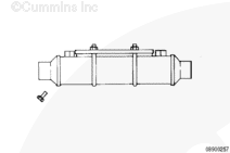
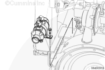
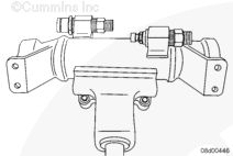
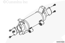
Plug one gear oil port and attach an air supply line to the other gear oil port with a quick disconnect fitting. Apply thread sealant to the threads to prevent leaks. Do not allow sealant to enter the gear oil cooler.
Troubleshooting with high pressure air presents the risk of equipment damage, personal injury, or death. Troubleshooting must be performed by trained, experienced technicians.
WARNING
Wear appropriate eye and face protection when using compressed air. Flying debris and dirt can cause personal injury.
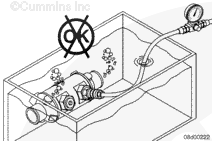
Attach a high-pressure air supply source (air cylinder or other suitable source) with an air pressure regulator and an inline shutoff valve to the quick disconnect fitting.
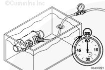
Set the regulator test pressure to 276 kPa [40 psi].
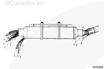
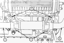
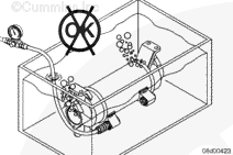
Submerge the gear oil cooler into a tank of water. Rotate the cooler to allow any trapped air to escape. Allow the cooler to remain submerged for 1 minute.
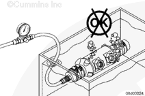
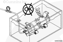
Fabricate a test fixture to seal the sea water connections, or use connector hoses with a quick disconnect air connection to supply a regulated test pressure of 276 kPa [40 psi] to the sea water side of the gear oil cooler.
When using solvents, acids, or alkaline materials for cleaning, follow the manufacturer’s recommendations for use. Wear goggles and protective clothing to reduce the possibility of personal injury.
WARNING
Some solvents are flammable and toxic. Read the manufacturer’s instructions before using.
WARNING
Wear appropriate eye and face protection when using compressed air. Flying debris and dirt can cause personal injury.
Drain the water from the cooler.
Flush the oil side of the cooler with clean solvent.
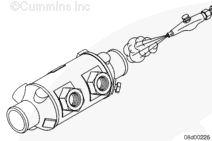
Plug one gear oil port and sensor ports, as needed.
Attach an air supply line to the other gear oil port with a quick disconnect fitting.
Apply thread sealant to the threads to prevent leaks.
Do not allow sealant to enter the gear oil cooler.
Attach a high-pressure air supply source, such as an air cylinder or other suitable source, with an air pressure regulator and an inline shutoff valve to the quick disconnect fitting.
Set the regulator test pressure to 276 kPa [40 psi].
Shut off the air supply and disconnect the air supply.
Remove the test fitting and install a plug. This is to keep water from contaminating the oil side of the cooler.
Fabricate a test fixture to seal the sea water connections, or use connector hoses with a quick disconnect air connection to supply a regulated test pressure of 276 kPa [40 psi] to the sea water side of the gear oil cooler.
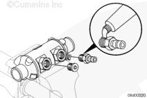
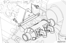
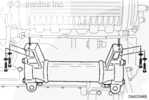
Coat the threads with thread sealant and install the two line fittings into the gear cooler, if removed. Be sure they are oriented in the same direction as they were removed.
Do not tighten the vise to the extent that the cooler case could be damaged.
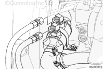
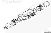
(1) Coat the threads with thread sealant and install the two line fittings into the gear cooler, if removed. They must be oriented in the same direction as they were removed.
(2) Install the oil temperature sensor on the right and the oil pressure sensor on the left.
Batteries can emit explosive gases. To reduce the possibility of personal injury, always ventilate the compartment before servicing the batteries. To reduce the possibility of arcing, remove the negative (-) battery cable first and attach the negative (-) battery cable last.
Hello, I'm Jack, a diesel engine fan and a blogger. I write about how to fix and improve diesel engines, from cars to trucks to generators. I also review the newest models and innovations in the diesel market. If you are interested in learning more about diesel engines, check out my blog and leave your feedback.
View all posts by Jack
 WARNING
  CAUTION


;)
;)
;)
;)
;)
;)
;)
;)
;)
;)
;)
;)
;)
;)
;)
;)
;)
;)
;)
;)
;)
;)
;)
;)
;)
;)
;)
;)
;)
;)
;)
;)
;)
;)
;)
;)
;)
;)
;)
;)
;)
;)
;)
;)
;)
;)
;)
;)
;)
;)