View Related Topic
Remove
TOC
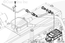
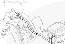
Disconnect the air line from the turbocharger actuator.
Disconnect the air line from the quick-connect fitting on the intake side of the engine.
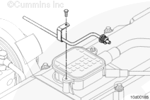
Remove the mounting capscrew from the crankcase breather.
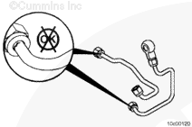
Disconnect the banjo fitting from the turbocharger control valve.
Use masking tape to tape the end of the air line and turbocharger control valve to prevent contamination.
Clean and Inspect for Reuse
TOC
Inspect the air line for wear or damage.
Inspect the o-rings for signs of damage or distortion.
Replace as necessary.
Install
TOC
Remove the masking tape from the ends of the turbocharger actuator supply line before installing the line.
Install the air line and the mounting capscrew to the crankcase breather.
Torque Value: 5 n.m [44 in-lb]
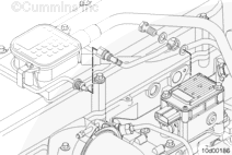
Connect the flexible elbow to the turbocharger control valve, use new sealing washers.
Torque Value: 8 n.m [71 in-lb]
Install the quick connect fitting to the air line.
Connect the air supply line to the turbocharger actuator.
Torque Value: 24 n.m [18 ft-lb]
Finishing Steps
TOC
Operate the engine and check for proper operation. Check for air leaks.
Last Modified: 15-Aug-2007
Published by Jack
Hello, I'm Jack, a diesel engine fan and a blogger. I write about how to fix and improve diesel engines, from cars to trucks to generators. I also review the newest models and innovations in the diesel market. If you are interested in learning more about diesel engines, check out my blog and leave your feedback.
View all posts by Jack


;)
;)
;)
;)
;)
;)
;)
;)
;)
;)
;)
;)