The external pressure tank used must meet SAE J10 and FMVSS121 standards, and have a safety pressure relief valve which opens between [150 to 175 psi]. Failure to use the proper pressure vessel and plumbing can result in property damage and serious personal injury.
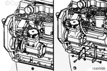
Air Compressor Diagnostic Test
Park the vehicle. Use a wheel chocks or an appropriate anti-roll divice to stabilize the vehicle.
Drain the vehicle.
Remove the air discharge hose and air govenor signal hose from the air compressor. Install pipe plugs into the air compressor unloader signal ports.
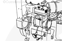
Plumb the air compressor discharge hose into an external pressure tank. The external pressure tank must be equipped with a pressure gauge and pressure relief valve. Make sure that the fittings are install with appropriate thread sealant and do not leak.
Start the engine and operate at rated engine speed.
Verify that the air compressor will build pressure in the external tank. If air pressure fails to build in the pressure tank, the air compressor has malfunctioned. Refer to Procedure 012-013 in Section 12.
NOTE: Once the external pressure tank pressure reaches 689 kPa [100 PSI], shut the engine down.
Monitor the pressure gage on the external tank for rapid leak down of the air pressure. If the air tank loses more than 138 kPa [20 PSI] in a 5 minute period, the pressure relief valve, intake valve, or exhaust valve has malfunctioned. Refer to Procedure 012-013 in Section 12.
NOTE: Do not cycle air accessories such as seats, doors, wipers, air bags, etc..
If there is any noticeable decrease of the air gauge readings or the air dryer cycled during the 10 minutes test, repair the leaks.
NOTE: Leaks in systems that hold pressure for 5 to 10 minutes may be hard to find.
Batteries can emit explosive gases. To reduce the possibility of personal injury, always ventilate the compartment before servicing the batteries. To reduce the possibility of arcing, remove the negative (-) battery cable first and attach the negative (-) battery cable last.
WARNING
When using a steam cleaner, wear safety glasses or a face shield, as well as protective clothing. Hot steam can cause serious personal injury.
WARNING
Do not remove the pressure cap from a hot engine. Wait until the coolant temperature is below 50°C [120°F] before removing the pressure cap. Heated coolant spray or steam can cause personal injury.
WARNING
Coolant is toxic. Keep away from children and pets. If not reused, dispose of in accordance with local environmental regulations.
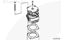
If the cylinder head are removed, inspect the bare and rotating components within the air compressor.
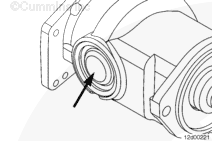
Inspect the air compressor bore for signs of scoring and polishing.
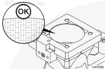
NOTE: A cross hatch honing pattern must be visible within the bore. If any part of the bore is scored or polished, the air compressor must be replaced.
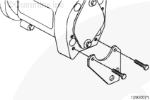
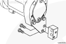
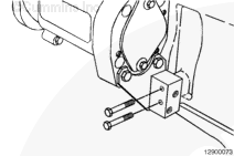
If internal damage to the rotating assembly (crankshaft, piston, and connecting rod) is suspected, the plug on the bottom of the air compressor must be removed to inpect the rotating assembly.
NOTE: A replacement plug and gasket kit is available for reassembling the air compressor.
Air Compressor Timing (for Single-Cylinder Air Compressor Only)
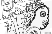
Rotate the engine so that the number 1 cylinder is at top dead center (TDC) on the compression stroke. This is done by aligning the timing mark on the fuel pump gear with the TDC mark.
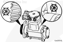
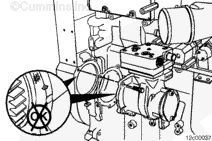
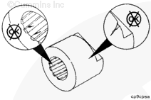
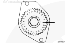
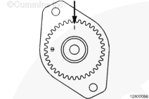
NOTE: There are two similar marks on the air compressor gear that look like “[I]” and “I”. The timing mark to be used when timing the air compressor to the engine is “I”.
Viewing the compressor from the gear end (with the compressor n a vertical position), rotate the gear so the “I” timing mark is at the 12-o’clock position. This will set the compressor at 60-degrees before top dead center of the compressor’s compression stroke.
NOTE: Some Holset® compressors have a divot or drilling on the housing at the 10-o’clock position; IGNORE this mark.
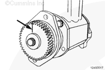
Viewing the compressor from the gear end (with the compressor in a vertical position), rotate the gear so the “I” timing mark is at the 3-o’clock position. The Cummins® single-cylinder air compressor will have a divot on the housing at the 3-o’clock position to aid in timing the compressor. Once the timing mark is at the 3-o’clock position, this will set the compressor at 60-degrees before top dead center of the compressor’s compression stroke.
Air Compressor Timing (for Single-Cylinder Air Compressor Only, Other than Holset® or Cummins®)
Locate TDC on the compressor crankshaft by removing the unloader valve or head. See the respective air compressor manual. TDC does not have to be exact. The system is tolerant of some misalignment.
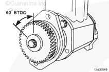
Rotate the compressor TDC mark to 60-degrees, or six teeth on a 36-tooth gear, before TDC. This is approximately 10-o’clock when viewed from the front of the air compressor.
Batteries can emit explosive gases. To reduce the possibility of personal injury, always ventilate the compartment before servicing the batteries. To reduce the possibility of arcing, remove the negative (-) battery cable first and attach the negative (-) battery cable last.
Hello, I'm Jack, a diesel engine fan and a blogger. I write about how to fix and improve diesel engines, from cars to trucks to generators. I also review the newest models and innovations in the diesel market. If you are interested in learning more about diesel engines, check out my blog and leave your feedback.
View all posts by Jack
 WARNING


;)
;)
;)
;)
;)
;)
;)
;)
;)
;)
;)
;)
;)
;)
;)
;)
;)
;)
;)
;)
;)
;)
;)
;)
;)
;)
;)
;)
;)
;)
;)
;)
;)
;)