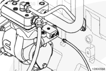
The air compressor governor location can vary. The air governor can be air compressor mounted or chassis mounted.
If the air pressure is being governed at either a higher or lower pressure than the equipment manufacturer’s specification, connect a regulated shop air pressure line to the air compressor governor air signal port.
NOTE: Be positive the gauge is accurate and the supply lines and fittings are in good condition before performing any air pressure checks. Use a master gauge of known accuracy to check the air pressure gauge.
NOTE: When performing the test, be sure the air system pressure does not exceed the manufacturer’s maximum allowable pressure.
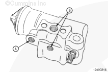
NOTE: Make sure the governor vent port (A) is open to the atmosphere. If this port is plugged, the air governor will malfunction.
Inspect the governor control lines for restrictions.
Drain the air system and install a gauge of known accuracy onto the unloader port (B) of the air governor. If the governor has two unloader ports, make sure one is plugged.
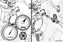
Start the engine and apply the brakes to initiate air compressor pumping. Note the governor cut-out pressure (pressure at which the compressor stops pumping).
Apply the brakes until the compressor starts to pump. Note the cut-in pressure.
NOTE: Zero pressure in the governor unloader line will allow the compressor to start pumping.
Allow the system to build pressure until the air compressor unloads.
Apply the brakes until the compressor starts to pump. Note the time it takes for the governor unloader port to go from system pressure to 0 kPa [0 psi]. The cycle should take less than 2 seconds.
Repeat steps three through six for a total of three runs.
Hello, I'm Jack, a diesel engine fan and a blogger. I write about how to fix and improve diesel engines, from cars to trucks to generators. I also review the newest models and innovations in the diesel market. If you are interested in learning more about diesel engines, check out my blog and leave your feedback.
View all posts by Jack


;)
;)
;)
;)
;)
;)