System Operation Description:
Use this procedure under the following situation:
• There is an active diagnostic code.
• There is an easily repeated diagnostic code that is associated with the vehicle speed circuit.
Refer to Troubleshooting, “Vehicle Speed Circuit – Calibrate” if the vehicle speed is being calibrated in ppm (pulses per mile) or PPKM (pulses per kilometer).
The following background information is related to this procedure:
The vehicle speed circuit consists of the vehicle speed source and associated wiring. The vehicle speed source is installed by the vehicle OEM. Usually, a sensor reads movement of the transmission output shaft from the teeth on a chopper wheel. The ECM converts the signal from the vehicle speed source into vehicle speed for the following functions:
• Cruise Control
• Idle Speed Control
• Progressive Shift
• Driver Reward
• Speedometer
• Battery Monitor Engine Speed Control
• PTO Operation
• Vehicle Speed Limiting
• Engine Retarding
• Idle Shutdown
• Secure Idle Theft Deterrent
• Trip Data
• Maintenance Data
To begin troubleshooting a vehicle speed problem, the following information must be determined:
The problem is electrical or the problem is a calibration problem.
Electrical problems would be an erratic speed
signal or no speed signal. A calibration problem
would be a stable ECM speed, but an inaccurate
ECM speed. Another calibration problem would be
a stable speedometer speed, but an inaccurate
speedometer speed.
If the problem is related to vehicle speed calibration, refer to Troubleshooting, “Vehicle Speed Circuit – Calibration” for calibrating the vehicle speed in PPKM (pulses per kilometer) or ppm (pulses per mile). The ECM Speedometer output signal is set to 18,600 PPKM (30,000 ppm) and the ECM speedometer output signal cannot be changed. All speedometers that are driven by the ECM output (J1/P1:36 & 37) must match the ECM (30,000 ppm) in order to operate properly.
The type of vehicle speed sensor that is installed on the vehicle must be determined.
Both single coil magnetic sensors and dual coil
magnetic sensors are commonly used. Caterpillar
recommends single coil magnetic sensors. Some of
the vehicles may provide the vehicle speed through
the transmission ECM.
You must determine if the vehicle speedometer is driven from the ECM.
The ECM can drive the speedometer through the connection to J1:36 (Speedometer Positive) and/or J1:37 (Speedometer Negative).
Note: The ECM may also drive the speedometer by a connection to the J1587 ATA data link or the J1939 data link, if the instrument cluster is capable of interpreting the signal.
Vehicle Speed Circuit Wiring
The vehicle speed signal is connected to the ECM at J1/P1:32 (Vehicle Speed In Positive) and J1/P1:33 (Vehicle Speed In Negative).
Speedometer Connection
If the speedometer is driven by the ECM output, the speedometer is connected to the following terminals:
• J1/P1:36 (Speedometer Positive)
• J1/P1:37 (Speedometer Negative)
Note: Some speedometers require only one of the ECM signal lines to operate. Other speedometers may require both of the ECM signal lines to operate.
Speedometer Special Test
If the vehicle speedometer is driven by ECM output, the speedometer circuit can be checked by using the electronic service tool. The “55 mph VSP/Speedometer Test” will drive the speedometer to approximately 55 mph under the following conditions:
• The “55 mph VSP/Speedometer Test” is activated.
• The circuit is operating properly.
• The speedometer is operating properly.
Note: While the test is active, the odometer will increment mileage.
Magnetic Sensors
A magnetic pickup will have only two wires if the magnetic pickup is a single coil magnetic sensor. Also, a magnetic pickup will have four wires if the magnetic pickup is a dual coil magnetic sensor. The magnetic pickup sensor does not require a power connection or a ground connection.
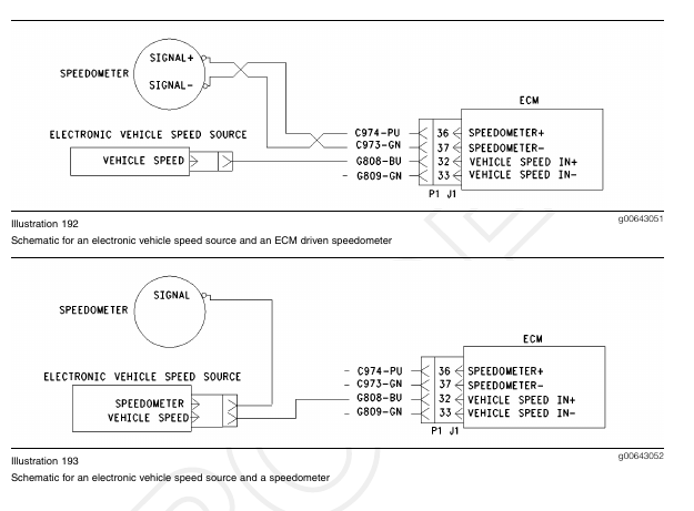
Vehicles with Electronic Vehicle Speed Sources
For these vehicles, the vehicle speed signal is provided by an electronic source. The signal is received over a single wire that is connected to J1/P1:32 (Vehicle Speed In Positive). No other connection should be made to this line. A speedometer is an example of a connection that should not be made to this line. For this type of signal, the J1/P1:33 (Vehicle Speed In Negative) should not be connected to the ECM in order to prevent introducing electrical noise into the circuit.
For vehicle speed problems on trucks that are equipped with either of these vehicle speed sources, first inspect the wiring from the electronic source to the engine ECM for open circuits or short circuits.

Test Step 1. Determine the Type of Connection
A. Determine if the wiring for the circuit is wired directly to the ECM or through the J1939 or J1587 data link.
B. Verify that the “Vehicle Speed Input” parameter is programmed to reflect the proper wiring.
Expected Result:
The suspect input is wired directly to the ECM.
Results:
• OK – The suspect input is wired directly to the ECM. Proceed to Test Step 2.
• J1939 data link – The suspect input is wired through the J1939 data link.
Repair: Refer to Troubleshooting, “Powertrain Data Link Circuit – Test”.
STOP.
• J1587 data link –
Repair: Refer to Troubleshooting, “ATA (SAE J1587 / J1708) Data Link Circuit – Test”.
STOP.
Test Step 2. Inspect Electrical Connectors and Wiring
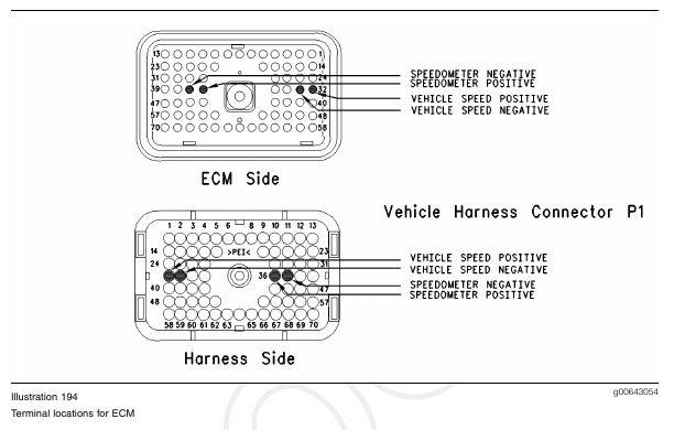
A. Thoroughly inspect the J1/P1 ECM connector, the firewall bulkhead connector and the terminals for vehicle speed (terminals 32 and 33) in the connectors. Refer to Troubleshooting, “Electrical Connectors – Inspect” for details.
B. Perform a 45 N (10 lb) pull test on each of the wires in the ECM connector that are associated with the vehicle speed sensor.
Refer to Illustration 194.
C. Check the ECM connector (allen head screw) for the proper torque of 6.0 N·m (55 lb in).
D. Check the harness and wiring for abrasion and pinch points from the sensor to the ECM.
Expected Result:
All connectors, pins and sockets should be completely coupled and/or inserted and the harness and wiring should be free of corrosion, abrasion or pinch points.
Results:
• OK – Proceed to Test Step 3.
• Not OK
Repair: Perform the following repair:
Repair the connectors or wiring and/or replace the connectors or wiring. Ensure that all of the seals are properly in place and ensure that the connectors are completely coupled.
Verify that the repair eliminates the problem.
STOP.
Test Step 3. Determine the Type of Vehicle Speed Problem
A. Perform a dynamometer test on the vehicle or perform a road test on the vehicle. Compare the vehicle speed on the status screen on ET against the speedometer. Also, compare the vehicle speed on the status screen against the actual vehicle speed. The actual vehicle speed can be measured on a dynamometer or the actual vehicle speed can be measured by a stopwatch.
B. Monitor the vehicle speed status on the electronic service tool while the vehicle is parked and the engine is running.
C. Operate various electrical devices in the vehicle while the vehicle speed is being monitored. In order to operate the various electrical devices, cycle the electrical devices to the ON position and the OFF position.
D. Increase the engine rpm a few times and decrease the engine rpm a few times.
Note: If the operation of a specific electrical device is producing a vehicle speed problem, the electrical device may be the source of an electrical noise problem. An electrical noise problem is also a possibility if increasing the engine rpm on a stationary vehicle produces a vehicle speed problem.
Expected Result:
Result 1 The speed that is displayed on the status screen and the speed of the ECM driven speedometer are stable and both speeds agree with the actual speed.
Result 2 The status screen and speed is stable, but incorrect.
Test Step 4. Use the Special Test to Check the Speedometer
A. Inspect the P1 ECM connector. Observe whether connections are present at either of the following terminals:
• P1:36 (Speedometer Positive)
• P1:37 (Speedometer Negative)
If there is a connection to either of the speedometer terminals continue with the procedure.
B. Connect the electronic service tool to the data link connector.
C. Access the “55 mph VSP/Speedometer Test” by accessing the following display screens in order:
• “Diagnostics”
• “Diagnostic Tests”
• “Special Test menu”
D. Activate the test and observe the speedometer.
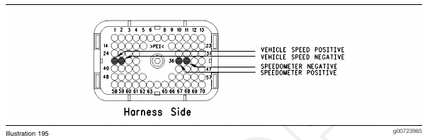
Note: Some types of speedometers only require one ECM signal line to be connected to the speedometer. Either of the ECM terminals can be used for these speedometers.
Refer to Illustration 195.
Expected Result:
The speedometer indicates 80 to 96 km/h (50 to 60 mph).
Results:
• OK – The ECM is providing the signal for the speedometer and the wiring and the speed are
OK. Send the vehicle to the OEM dealer for repair of the speedometer. STOP.
• Not OK – The ECM is not connected to the speedometer.
Repair: Perform the following repair:
If the ECM is not connected to the OEM speedometer, send the vehicle to the OEM dealer for repair of the speedometer.
STOP.
• Not OK – The speedometer does not show any vehicle speed.
Repair: If OEM truck wiring diagrams are available, trace the wiring to the speedometer and repair the speedometer, as required.
STOP.
• Not OK – The vehicle speed is not within the proper range.
Repair: Perform the following diagnostic
procedure:
Troubleshooting, “Vehicle Speed Circuit – Calibrate”
STOP.
Test Step 5. Determine the Type of Vehicle Speed Circuit
A. Inspect the vehicle wiring for the type of vehicle speed circuit that is being used.
Compare the vehicle speed circuit with the detailed circuit schematics:
Schematic 1 Refer to Illustration 189.
Schematic 2 Refer to Illustration 190.
Schematic 3 Refer to Illustration 191.
Schematic 4 Refer to Illustration 192.
Schematic 5 Refer to Illustration 193.
Select the schematic that is similar to the circuit that is being repaired.
Expected Result:
The vehicle speed circuit is similar to Schematic 1, 2, or 3.
Results:
• OK – Proceed to Test Step 6.
• Not OK – The vehicle speed circuit is similar to Schematic 4 or 5. Proceed to Test Step 8.
Test Step 6. Measure Vehicle Speed Sensor Resistance at the Sensor
A. Disconnect the vehicle speed sensor from the vehicle harness.
B. Thoroughly inspect the connector. Ensure that the connector terminals are free of corrosion and ensure that the connector terminals are fully seated into the housing of the connector. Repair the connector terminals or replace the connector terminals, as required.
C. Measure the resistance between the two terminals of the sensor connector. The sensor resistance measurement should be 100 to 4500 Ohms.
D. Reverse the meter leads and measure the resistance. Switching the probes should not change the resistance measurement by more than 10 Ohms.
Expected Result:
The sensor resistance that is measured is between 100 and 4500 Ohms and the sensor resistance that is measured is within 10 Ohms with the meter probes in either position.
Results:
• OK – Reconnect the sensor to the vehicle harness. Proceed to Test Step 7.
• Not OK
Repair: Perform the following repair:
If the sensor is damaged, replace the damaged sensor or send the vehicle to the OEM dealer for repairs.
Verify that any repair eliminates the problem.
STOP.
Test Step 7. Inspect the Passive Magnetic Speed Sensor for Vehicle Speed.
A. Remove the vehicle speed sensor from the transmission and inspect the vehicle speed sensor for steel shavings, debris, or damage.
Note: Shavings and debris on the sensor may occur unless the transmission fluid is drained and replaced according to the maintenance schedule.
B. Wipe off the sensor until the sensor is clean. Test the sensor according to the manufacturer’s instructions. The sensor is OEM supplied.
Note: If the gap between the vehicle speed sensor and the chopper wheel is too small, the sensor may be damaged. Also if the gap between the vehicle speed sensor and the chopper wheel is too small, the sensor may create a signal due to the vibration of the chopper wheel. This will cause a vehicle speed signal when the vehicle is parked. If the vehicle is parked and a vehicle speed signal is produced, back out the sensor from the wheel until the signal disappears. Use caution. backing out the sensor too far may cause a loss of the vehicle speed signal. Back out the sensor no more than one turn to one and one quarter turns.
Expected Result:
The vehicle speed sensor is correctly installed and undamaged.
Results:
• OK – Proceed to Test Step 8.
• Not OK
Repair: Perform the following repair:
If the sensor is damaged, replace the damaged sensor or send the vehicle to the OEM dealer for repairs.
Verify that any repair eliminates the problem.
STOP.
Test Step 8. Test ECM Vehicle Speed Inputs by Using the Speedometer Special Test.
A. Turn the key switch to the OFF position.
B. Fabricate two jumper wires 100 mm (4 inch) long.
Crimp a Deutsch pin to each end of the wires.
C. Connect a 140-2266 Cable (Seventy-Pin Breakout) between the J1 and P1 ECM connectors.
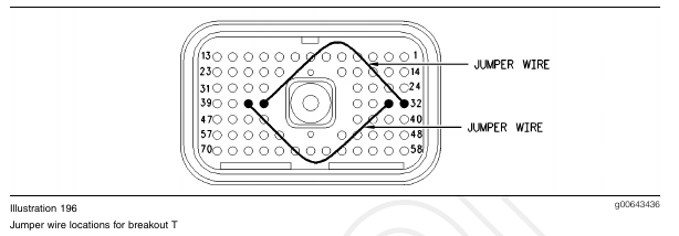
D. Install one jumper into the breakout T in order to connect terminal 36 (Speedometer Positive) to terminal 32 (Vehicle Speed In Positive). Install the other jumper into the breakout T in order to connect terminal 37 (Speedometer Negative) to terminal 33 (Vehicle Speed In Negative).
Refer to Illustration 196.
E. Turn the key switch to the ON position.
F. Connect the electronic service tool to the data link connector.
G. Access the “55 mph VSP/Speedometer Test” by accessing the following display screens in order:
• “Diagnostics”
• “Diagnostic Tests”
• “Special Test menu”
H. Activate the test and observe the vehicle speed on the vehicle speed status screen.
Expected Result:
The electronic service tool indicates a constant vehicle speed between 80 to 96 km/h (50 to 60 mph) when the jumper wires from the speedometer circuit are connected.
Results:
• OK – The ECM is operating correctly. The source of the problem is either the wiring or the source of the problem is the vehicle speed sensor.
Repair: Perform the following repair:
If the sensor is damaged, replace the damaged sensor or send the vehicle to the OEM dealer for repairs.
Verify that any repair eliminates the problem.
STOP.
• Not OK – Recheck the connections of the jumper wires. Leave the jumper wires installed in the breakout T. Disconnect the breakout T. Proceed to Test Step 9.
Test Step 9. Test the ECM Vehicle Speed Inputs When the Test ECM is Installed
A. Connect a test ECM and reconnect the breakout T.
B. Install one jumper into the breakout T in order to connect terminal 36 (Speedometer Positive) to terminal 32 (Vehicle Speed In Positive). Install the other jumper into the breakout T in order to connect terminal 37 (Speedometer Negative) to terminal 33 (Vehicle Speed In Negative).
Refer to Illustration 196.
C. Turn the key switch to the ON position.
D. Access the “55 mph VSP/Speedometer Test” by accessing the following display screens in order:
• “Diagnostics”
• “Diagnostic Tests”
• “Special Test menu”
E. Activate the test and observe the vehicle speed on the vehicle speed status screen.
Expected Result:
The electronic service tool indicates a constant vehicle speed between 80 to 96 km/h (50 to 60 mph) when the jumper wires from the speedometer circuit are connected.
Results:
• OK
Repair: Perform the following repair:
Reconnect the suspect ECM. If the problem returns with the suspect ECM, replace the ECM.
STOP.
• Not OK – Recheck the connectors. Continue troubleshooting until original condition is resolved.
STOP.