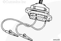
To reduce the possibility of connector damage, do not use probes or leads other than Part Number 3822758. The leads must fit tightly in the connector without expanding the pins in the connector.
Disconnect the OEM harness connector from the ECM. Refer to Procedure
Insert a test lead into pin 10 (switch common +5-VDC supply) of the OEM harness connector. Insert the other test lead into pin 6 (active idle signal). Connect the alligator clips to the multimeter probes.
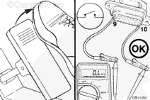
Move the test lead from pin 6 to pin 9 (active off-idle signal). Slowly depress the foot pedal and measure the resistance.
The multimeter
must show 10 ohms or less for separate sensor/switch pedals and 125 ohms or less for integrated sensor/switch pedals when in the OFF-IDLE zone of the pedal travel.
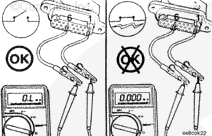
Install a test lead into pin 6 (active idle signal). Clip the lead to the multimeter. Touch the other multimeter probe to ground and measure the resistance.
Move the test lead from pin 1 to pin 2, then pin 3.
The multimeter
must show an open circuit (100k ohms or more) in all pins.
If the multimeter shows a closed circuit in any pin, there is a short circuit between wire number 6 (active idle circuit) and any other wire that measured a closed circuit. Repair the OEM harness according to the vehicle manufacturer’s procedures.
Connect the clutch switch and idle validation switch when repair is completed.
Move the test lead from pin 1 to pin 2, then pin 3.
The multimeter
must show an open circuit (100k ohms or more) in all pins.
If the multimeter shows a closed circuit in any pin, there is a short circuit between wire number 9 and any other wire that measured a closed circuit. Repair the OEM harness according to the vehicle manufacturer’s procedures.
Connect the clutch switch and idle validation switch when repair is completed.
Move the test lead from pin 1 to pin 2, then to pin 3.
The multimeter must show an open circuit (100k ohms or more) in all pins.
If the multimeter shows a closed circuit in any pin, there is a short circuit between wire number 10 and any other wire that measured closed circuit. Repair the OEM harness according to the vehicle manufacturer’s procedures.
Connect the clutch switch and idle validation switch when repair is completed.
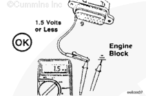
Turn keyswitch ON. Adjust the multimeter to measure voltage. Insert a test lead into pin 6 (active idle signal). Clip the lead to the multimeter positive (+) probe. Connect the multimeter negative (-) probe to ground and measure the voltage.
Move the test lead from pin 9 to pin 10 (switch common +5-VDC supply). Touch the multimeter negative (-) lead to ground and measure the voltage.
The voltage
must be 1.5 VDC or less.
If more than 1.5 VDC are measured at any pin, there is a short circuit between that pin and a wire carrying power in the OEM harness. Repair the OEM harness according to the manufacturer’s instructions.
Connect all components after the repair is complete.
Hello, I'm Jack, a diesel engine fan and a blogger. I write about how to fix and improve diesel engines, from cars to trucks to generators. I also review the newest models and innovations in the diesel market. If you are interested in learning more about diesel engines, check out my blog and leave your feedback.
View all posts by Jack
 CAUTION


;)
;)
;)
;)
;)
;)
;)
;)
;)
;)
;)
;)
;)
;)
;)
;)
;)
;)
;)
;)
;)
;)
;)
;)
;)
;)
;)
;)
;)
;)
;)
;)
;)
;)
;)
;)