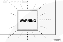
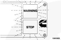
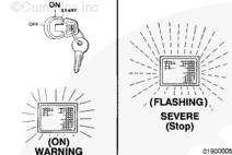
The Gas Plus engines are equipped with an engine protection system. The system monitors critical engine temperatures and pressures and will log diagnostic faults when an over- or under normal operating condition occurs. If an out of range condition exists, and engine derate action is to be initiated, the operator will be alerted by an in-cab WARNING lamp. The WARNING lamp will blink or flash when out of range conditions continue to get worse. When the red STOP lamp is illuminated, the driver must pull to the side of the road, when it is safe to do so, to reduce the possibility of engine damage.
The engine protection system monitors the following inputs:
Coolant temperature
Coolant level
Oil pressure
Intake manifold temperature
Engine overspeed
Fuel temperature.
NOTE: Engine power and speed will be gradually reduced depending on the level of severity of the observed condition. The engine protection system will not shut down the engine unless the engine protection shutdown feature has been enabled.
Engine Protection Shutdown – B Gas Plus, B LPG Plus, B Gas International, C Gas Plus.
This feature automatically shuts off the engine when the temperature, pressure, or coolant level sensors indicate the engine is operating over or under normal operating conditions.
The red STOP lamp in the cab will flash for 30 seconds prior to shutdown to alert the driver.
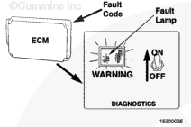
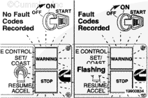
While a fault condition is being detected, the fault lamp will turn ON or ON FLASHING. The ECM will turn the lamp ON for warning faults and ON FLASHING for more severe faults that can affect engine operation and need immediate attention. Active fault conditions must be corrected as soon as possible.
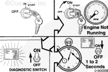
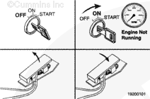
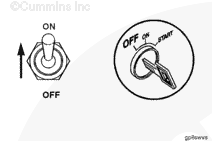
To determine an active fault code, shut off the engine and turn the ignition switch to the ON position (engine not running). Toggle the diagnostic switch to the ON position for one or two seconds then release it. If the fault lamp lights after toggling the diagnostic switch then there is an active fault or faults.
NOTE: The diagnostic switch is an OEM supplied option.
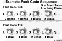
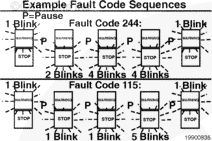
If there is an active fault, after releasing the diagnostic switch there will be a short pause followed by the first fault code. Fault codes consist of three digits with up to nine flashes per each digit. There is a short pause between each digit of the fault code. Once the three digits are flashed, there is a longer pause followed by a repeating of the same fault code sequence.
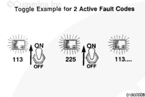
Toggling the diagnostic switch will advance to the next fault code. Once all active fault codes have been displayed, the fault code display sequence will be repeated starting from the first fault code. If only one active fault is recorded, the system will continuously display the same fault code when the diagnostic switch is toggled. Refer to a Cummins Authorized Repair Facility.
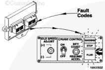
The control system can show and record operation anomalies that present themselves as fault codes. These codes will make troubleshooting easier. The fault codes are recorded in the electronic control module (ECM). They can be read using the fault lamps in the dash or with the INSITE™ electronic service tool.
NOTE: Not all engine control system anomalies are shown as fault codes.
When a fault condition is detected, the fault lamp will turn ON or ON FLASHING.
A lamp ON condition is for warning faults, and a ON FLASHING condition is for more severe faults that can have an effect on engine operation and need immediate attention. Active fault condition must be corrected as soon as possible.
To determine an active fault code, shut off the engine and turn the ignition switch to the ON position (engine not running). Toggle the diagnostic switch to the ON position for one to two seconds and then release it. If the fault lamp lights after toggling the diagnostic switch then there is an active fault or faults.
NOTE: The diagnostic switch is an OEM supplied option.
If there is an active fault, after releasing the diagnostic switch, there will be a short pause followed by the first fault code. Fault codes consist of three digits with up to nine flashes per each digit. There is a short pause between each digit of the fault code and once the three digits are flashed there is a longer pause followed by a repeating of the same fault code sequence.
Toggling the diagnostic switch will advance to the next fault code. Once all the fault codes have been displayed, the fault code display sequence will be repeated starting from the first fault code. If only one active fault is recorded, the control system will continuously display the same fault code when the diagnostic switch is toggled. Refer to a Cummins Authorized Repair Facility.
The system can record and display detectable fault conditions within the system and circuits.
When a fault condition is detected, the Governor Control Module fault lamp will turn ON or ON FLASHING. The Governor Control Module will turn the lamp ON for warning faults, and ON FLASHING for more severe faults that can have an effect on engine operation and need immediate attention. Active fault conditions must be corrected as soon as possible.
To determine an active fault code, shut off the engine and turn the ignition switch to the ON position (engine not running). Press the accelerator pedal twice quickly. The Governor Control Module should begin flashing the Governor Control Module faults on the diagnostic lamp.
B Gas Plus, B LPG Plus, B Gas International, and C Gas Plus
The Gas Plus engine control system can show and record operation anomalies that present themselves as fault codes. These codes will make troubleshooting easier. The fault codes are recorded in the electronic control module (ECM). They can be read using the fault lamps in the dash or with the INSITE™ electronic service tool.
NOTE: Not all engine control system anomalies are shown as fault codes.
All fault codes recorded will be either active (fault code is currently active on the engine) or inactive (fault code was active at some time, but at the moment, is not active).
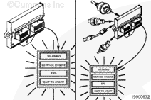
Most, but not all, of the electronic fault codes will light a lamp when they are active. There are three possible lamps that can be illuminated when a fault code is active.
The WARNING or CHECK ENGINE lamp is yellow and indicates the need to repair the fault at the first available opportunity. This lamp will also illuminate when an engine maintenance function needs to be performed.
The STOP or STOP ENGINE lamp is red and indicates the need to stop the engine as soon as it can be safely done. The engine should remain shut down until the fault can be repaired.
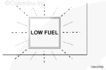
Some vehicles have a low fuel pressure lamp. The low fuel pressure lamp will illuminate if the primary fuel pressure sensor detects that the supply pressure to the engine is below specifications.
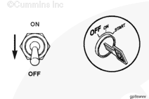
To check for active engine electronic system fault codes and maintenance indicator codes, turn the ignition switch to the OFF position, and move the diagnostic switch to the “ON” position, or connect the shorting plug into the diagnostic connector.
The fault code will flash in the following sequence:
A yellow WARNING lamp will flash
There is a short one or two second pause
The fault code will flash on the red STOP lamp
There is a short one or two second pause between each number.
When the number has finished flashing in red, a yellow WARNING lamp will appear again. The fault code will repeat the same sequence until cycling to the next active fault code.
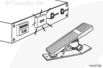
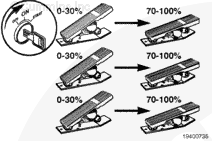
The throttle activated diagnostic switch is intended to eliminate the need for a dash mounted diagnostic switch, which is used to activate the diagnostic mode to display active fault codes in a sequence of flashing lamps. The throttle activated diagnostic switch feature provides a simple sequence of throttle movements that activate the diagnostic mode.
When the engine is not running, the ignition switch is turned on, and the feature flag is enabled, a sequence of three throttle cycles will activate the diagnostic mode. The increment/decrement switch can be used to navigate to the next or previous fault code. In case these switches are not available, a throttle cycle will also increment to the next fault.
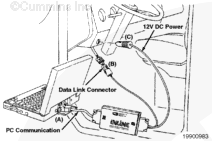
Additional fault code information can be obtained by using the INSITE™ electronic service tool. The snapshot data records the value or state of the control system sensors and switches at the time a fault code occurred. Either set of data is stored for the first occurrence of the fault, since it was last cleared, and for the most recent occurrence. This data can be very valuable when trying to recreate or determine engine operating conditions at the time of the fault.
Hello, I'm Jack, a diesel engine fan and a blogger. I write about how to fix and improve diesel engines, from cars to trucks to generators. I also review the newest models and innovations in the diesel market. If you are interested in learning more about diesel engines, check out my blog and leave your feedback.
View all posts by Jack
;)
;)
;)
;)
;)
;)
;)
;)
;)
;)
;)
;)
;)
;)
;)
;)
;)
;)
;)
;)
;)
;)
;)
;)
;)
;)
;)
;)
;)
;)
;)
;)
;)
;)
;)
;)
;)
;)