M11 Series – Service Manual – 004-001   Cam Follower Assembly

Remove

TOC

Remove the cylinder head. Refer to Procedure
002-004

Remove the nuts and washers from the cam follower assembly supports.

SMALL | MEDIUM | LARGE


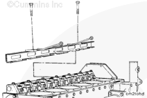
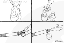
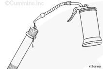
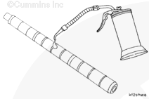
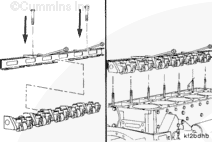
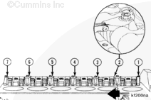
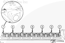
Install the cam follower assembly installation and removal tool, Part No. 3824519. Slide the tool under the assemblies with the supports located in the cutouts on the bottom surface of the tool.

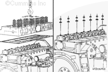
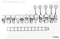
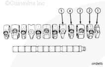
NOTE: The cam follower assembly consists of two shaft assemblies with a common center support.

Secure the tool to the assemblies by hand-tightening the screws on top of the tool.

SMALL | MEDIUM | LARGE


Lift both ends of the cam follower assemblies to remove them from the engine.

Set the assemblies on a flat surface. Loosen the two screws on top of the tool, and remove the tool from the cam follower assemblies.

SMALL | MEDIUM | LARGE


Install two M10 x 1.50 nuts on each stud.

Tighten the nuts together.

Turn the bottom nut
counterclockwise to remove the stud.

NOTE: The cam follower studs have an internal oil passage to supply the cam followers with lubricating oil. The studs
must be removed and checked.

SMALL | MEDIUM | LARGE
   

Disassemble

TOC

Separate the two shafts from the center support.

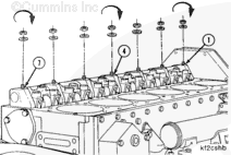
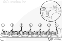
NOTE: The cam follower levers
must be installed in the same position they were removed from. Mark both of the end supports, the center support and all of the cam followers to identify their location when they are removed. The end supports are
not interchangeable. The center support is
not interchangeable with any of the other inner supports.

SMALL | MEDIUM | LARGE


Remove the end supports (1) from the shafts.

Remove the cam followers and supports from both shafts.

  • Valve cam follower (2)
  • Injector cam follower (3
  • Valve cam follower (4)
  • Shaft support (5)

SMALL | MEDIUM | LARGE
   

Clean

TOC

Clean the cam follower parts with solvent and dry with compressed air.

Make sure the oil passages in the cam followers and the cam follower studs are clean.

SMALL | MEDIUM | LARGE
   

Inspect for Reuse

TOC

Inspect the cam followers for cracks or other damage.

A lower case “m” stamped on the end of the cam follower pin identifies the improved pin first used on engine serial number 34842235.

Refer to Camshaft Reuse Guidelines, Bulletin
3666052, for inspection criteria of cam follower rollers.

SMALL | MEDIUM | LARGE


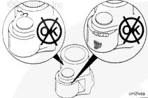
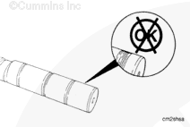
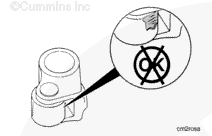
Inspect the cam follower sockets for excessive wear.

If excessive wear is found in the cam follower sockets, the push rods
must be inspected. Refer to Procedure
004-014.. Use the Overhead Reuse Guidelines, Bulletin 3810388, to identify wear patterns and excessive wear.

Replace all parts that do
not meet the reuse guidelines.

SMALL | MEDIUM | LARGE


Inspect the cam follower shafts for scores or damage.

SMALL | MEDIUM | LARGE


Inspect the cam follower rollers for flat spots, freedom of rotation, or other damage.

SMALL | MEDIUM | LARGE


Measure the cam follower roller side clearance.

Cam Follower Roller Side Clearance
mm in
0.19 MIN 0.007
0.65 MAX 0.026

SMALL | MEDIUM | LARGE


Use clean 15W-40 oil to check the oil flow through the cam followers.

SMALL | MEDIUM | LARGE


Use clean 15W-40 oil to check the oil flow through the cam follower studs.

SMALL | MEDIUM | LARGE
   

Assemble

TOC

Use clean 15W-40 oil to lubricate the cam followers and shafts.

SMALL | MEDIUM | LARGE


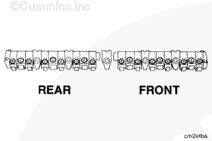
The cam followers, supports and shafts
must be installed in the same position from which they were removed. The shaft end supports are
not interchangeable.

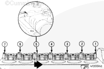
Install the end support (1) on the shaft.

Install the cam followers on the shaft in the following sequence:

  • Valve cam follower (2)
  • Injector cam follower (3)
  • Valve cam follower (4
  • Shaft support (5)

SMALL | MEDIUM | LARGE


Install the two cam follower shaft assemblies in the common center support (6).

NOTE: The common center support (6) has a locating dowel hole. The other inner supports do
not have this hole.

SMALL | MEDIUM | LARGE
   

Install

TOC

Install the cam follower studs with two M10 x 1.50 nuts tightened together.

Tighten the studs.

Torque Value:  34  n.m  [25 ft-lb]

Remove the two nuts.

SMALL | MEDIUM | LARGE


Install cam follower assembly installation and removal tool, Part No. 3824519, onto the cam follower assemblies.

NOTE: Before installing the cam follower assemblies, the cylinder head deck
must be cleaned. Refer to Procedure
002-004.

SMALL | MEDIUM | LARGE


Supports one, four, and seven are doweled. The supports
must align with the dowel pins in the cylinder block.

Install the cam follower assemblies on the studs.

Remove the service tool.

Install the washers and nuts on each stud.

Tighten the nuts on supports one, four, and seven.

Torque Value:  47  n.m  [35 ft-lb]

SMALL | MEDIUM | LARGE


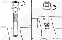
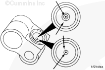
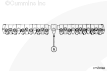
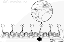
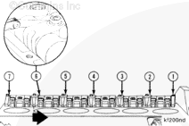
Install a 0.76-mm [0.030 in] feeler gauge between the No. three support and the exhaust lever for cylinder No. three. Push the No. three support toward the No. four support.

Tighten the No. three support nut.

Torque Value:  47  mm  [35 ft-lb]

SMALL | MEDIUM | LARGE


Install a 0.76-mm [0.030 in] feeler gauge between the No. two support and the intake lever for cylinder No. two. Push the No. two support toward the No. three support.

Tighten the No. two support nut.

Torque Value:  47  n.m  [35 ft-lb]

SMALL | MEDIUM | LARGE


Measure side clearance between the No. one and two supports.

Cam Follower Side Clearance Between Supports
mm in
0.76 MIN 0.030

SMALL | MEDIUM | LARGE


Install the 0.76-mm [0.030 in] feeler gauge between the No. five support and the exhaust lever for cylinder No. four. Push the No. five support toward the No. four support.

Tighten the No. five support nut.

Torque Value:  47  n.m  [35 ft-lb]

SMALL | MEDIUM | LARGE


Install the 0.76-mm [0.030 in] feeler gauge between the No. six support and the intake lever for cylinder No. five. Push the No. six support toward the No. five support.

Tighten the No. six support nut.

Torque Value:  47  n.m  [35 ft-lb]

SMALL | MEDIUM | LARGE


Measure the side clearance between the No. six and seven supports.

Cam Follower Side Clearance Between Supports
mm in
0.76 MIN 0.030

SMALL | MEDIUM | LARGE


Install the cylinder head. Refer to Procedure
002-004.

Operate the engine and check for leaks.

SMALL | MEDIUM | LARGE
Last Modified:  14-Sep-2007