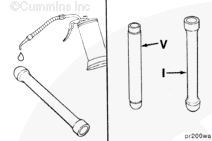
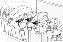
NOTE: Mark the position of the valve push tubes and injector push rods as they are removed. The push tubes and push rods must be installed in the same positions when the engine is assembled.
Loosen the rocker lever adjusting screws, and remove the valve push tubes and injector push rods.
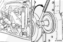
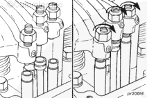
Hold the push tubes and push rods while loosening the adjusting screws. Do not let them fall into the engine while rotating the accessory drive pulley.
NOTE: Some push tubes and rods are under compression because the valves are open. Rotate the crankshaft clockwise with the accessory drive pulley to relieve the spring tension.
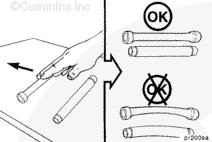
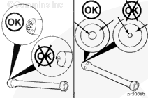
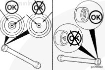
Inspect the seating pattern in the socket for excessive wear.
Inspect the ball end for excessive wear.
If excessive wear is found on the ball end, the cam follower sockets must be inspected. Refer to Procedure 007-009. Use the Overhead Reuse Guidelines, Bulletin 3810388, to identify wear patterns and excessive wear.
Replace all parts that do not meet the reuse guidelines.
Hello, I'm Jack, a diesel engine fan and a blogger. I write about how to fix and improve diesel engines, from cars to trucks to generators. I also review the newest models and innovations in the diesel market. If you are interested in learning more about diesel engines, check out my blog and leave your feedback.
View all posts by Jack


;)
;)
;)
;)
;)
;)
;)
;)
;)
;)
;)
;)
;)
;)
;)
;)
;)
;)
;)
;)