Do not straighten a bent fan blade or continue to use a damage fan. A bent or damaged fan blade can fail during operation and cause personal injury or property damage.
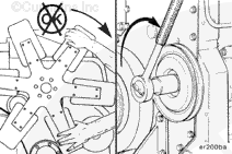
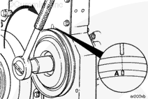
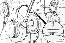
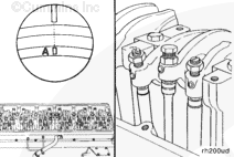
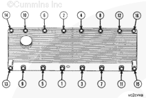
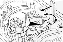
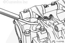
The valve set marks are located on the accessory drive pulley. The marks align with a pointer on the gear housing.
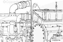
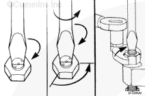
Use the accessory drive shaft to rotate the crankshaft.
For CELECT™ and CELECT™ Plus Engines, when the “A” mark is aligned with the pointer, the intake and exhaust valves for cylinder number 1 must be closed. The injector plunger for cylinder number 1 must be at the bottom of its stroke. If these conditions are not correct, cylinder number 6 must be ready to check. Check the injector and valves on the cylinder that both the intake and exhaust valve rocker levers can be “rattled” by hand or the push tubes can be freely rotated.
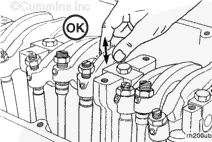
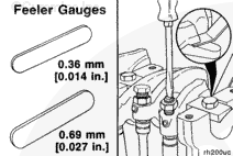
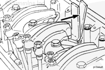
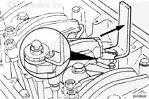
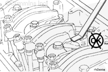
Using a set of feeler gauges, measure the amount of valve lash clearance between the crosshead and rocker lever nose. Measure and record the intake and exhaust valve lash. If the valve lash is not within the specifications listed below, the valves must be adjusted.
NOTE: All adjusting screws must be tight to get an accurate measurement.
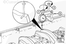
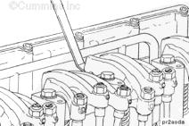
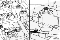
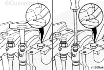
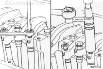
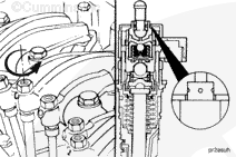
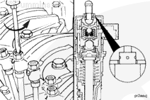
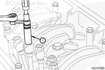
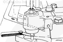
For measuring injector lash, install the dial indicator and the support from injector travel measurement kit, Part Number 3823610, or equivalent, so the extension, Part Number 3823595, or equivalent, for the dial indicator is on top of the injector rocker lever directly over the socket on the cylinder being checked.
Securely tighten the thumb screw (1) and the hold down capscrews (2 and 3) in place.
The injector plunger is under spring tension. Do not allow the tool to slip. Serious personal injury can result.
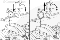
Actuate the injector plunger three or four times to make sure the fuel has been removed from the injector assembly. Allow the lever to return slowly to prevent damage to the dial indicator.
Actuate the lever again; set the dial indicator at zero “0” while holding the injector plunger to the bottom of its travel.
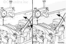
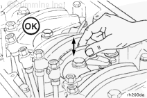
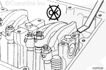
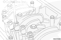
Check the valve rocker levers on cylinder number 5 to see if both valves are closed.
Both valves are closed when both rocker levers are loose and can be moved from side to side. If both valves are not closed, start with cylinder number 2.
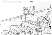
Using a set of feeler gauges, measure the amount of clearance (lash) between the crosshead and rocker lever nose for the cylinder being measured. Measure and record both the intake and exhaust rocker lever lash.
Valves, injectors, and engine brakes must be correctly adjusted for the engine to operate efficiently. Valve, injector, and engine brake adjustment must be performed using the values listed in this section. The accompanying table gives the adjustment specifications.
If the valves and injectors have been adjusted during troubleshooting or before this scheduled interval, adjustment is not required at this time.
Valve, Injector, and Engine Brake Adjustment Specifications
mm
in
Intake Valve
0.36
0.014
Exhaust Valve
0.69
0.027
Engine Brake
0.38
0.015
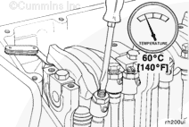
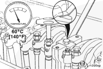
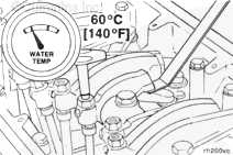
All valve and injector adjustments must be made when the engine is cold (any stabilized coolant temperature at 60°C [140°F] or below).
Do not straighten a bent fan blade or continue to use a damage fan. A bent or damaged fan blade can fail during operation and cause personal injury or property damage.
The valve set marks are located on the accessory drive pulley. The marks align with a pointer on the gear cover.
Use the accessory driveshaft to rotate the crankshaft.
NOTE: Set the injector on the same cylinder before setting valves.
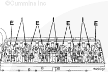
The valves and injectors on the same cylinders are adjusted at the same index mark on the accessory drive pulley.
One pair of valves and one injector are adjusted at each pulley index mark before rotating the accessory drive to the next index mark.
Two crankshaft revolutions are required to adjust all the valves and injectors.
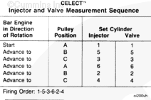
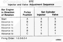
Injector and Valve Measurement Sequence
Bar Engine in Direction of Rotation
Pulley Position
Set Cylinder
Injector
Valve
Start
A
1
1
Advance to
B
5
5
Advance to
C
3
3
Advance to
A
6
6
Advance to
B
2
2
Advance to
C
4
4
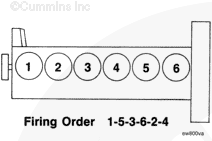
Firing Order: 1-5-3-6-2-4
The adjustment can begin on any valve set mark. In the following example, the adjustment will begin on the “A” valve set mark with cylinder number 1 valves closed and ready for adjustment.
Rotate the accessory drive clockwise until the “A” valve set mark on the accessory drive pulley is aligned with the pointer on the gear cover.
When the “A” mark is aligned with the pointer, the intake and exhaust valves for cylinder number 1 must be closed. If these conditions are not correct, cylinder number 6 injector and valves must be ready to set. Set the injector and valves on the cylinder so that both the intake and exhaust valve rocker lever arms are loose and can be moved from side-to-side.
Both valves are closed when both rocker levers are loose and can be moved from side-to-side.
NOTE: Do not use excessive force when bottoming the plunger.
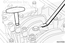
Loosen the injector adjusting screw locknut. Using a screwdriver (box end wrench if equipped with engine brakes) and the adjusting screw, bottom the injector plunger three or four times to remove the fuel.
Turn the adjusting screw in until you can feel it just bottom the plunger.
Back out the adjusting screw two flats, 120 degrees. Hold the adjusting screw, and tighten the locknut.
With the “A” valve set mark aligned with the pointer on the gear cover and both valves closed on the cylinder to be adjusted, loosen the adjusting screw locknuts on the intake and exhaust valves.
Two different methods for establishing valve lash clearance are described below. Either method can be used; however, the torque wrench method has proven to be the most consistent. It eliminates the need to feel the drag on the feeler gauge.
Torque Wrench Method: Use the inch-pound torque wrench, Part Number 3376592, or equivalent, normally used to set preload on top-stop injectors, and tighten the adjusting screw.
Torque Value: 0.7 n.m [6 in-lb]
Touch Method: Tighten the adjusting screw until a slight drag is felt on the feeler gauge.
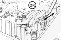
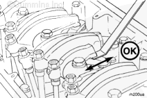
After tightening the locknut to the correct torque value, check to make sure the feeler gauge will slide backward and forward between the crosshead and the rocker lever with only a slight drag.
If using the touch method, attempt to insert a feeler gauge that is 0.03-mm [0.001-in] thicker between the crosshead and the rocker lever pad. The valve lash is not correct when a thicker feeler gauge will fit.
After adjusting the injector, valves, and engine brakes (if equipped) on the appropriate cylinder, rotate the accessory drive pulley, and align the next valve set mark with the pointer on the gear cover.
Valves and injectors must be correctly adjusted for the engine to operate efficiently. Valve and injector adjustment must be performed using the values listed in this section. The accompanying table gives the adjustment limits for STC engines.
Adjust the valves and the injectors at each 1,500 hour maintenance interval. If the valves and injectors have been adjusted during troubleshooting or before the 1,500 hour scheduled maintenance interval, adjustment is not required at this time.
mm
in
Intake Valve
0.35
0.014
Exhaust Valve
0.68
0.027
All overhead, valve and injector, adjustments must be made when the engine is cold, any stabilized coolant temperature at 60°C [140°F] or below.
Do not straighten a bent fan blade or continue to use a damaged fan. A bent or damaged fan blade can fail during operation and cause personal injury or property damage.
The valve set marks are located on the accessory drive pulley. The marks align with a pointer on the gear cover.
Use the accessory drive shaft to rotate the crankshaft.
The adjustment can begin on any valve set mark. In the following example the adjustment will begin on the “A” valve set mark with cylinder number five valves closed and cylinder number three injector ready for adjustment.
When the “A” mark is aligned with the pointer, the intake and exhaust valves for cylinder number five must be closed. If these conditions are not correct, cylinder number four injector and cylinder number two valves must be ready to set.
Both valves are closed when both rocker levers are loose and can be moved from side to side.
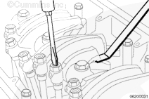
Loosen the injector adjusting screw locknut on cylinder number 3. Tighten the adjusting screw until all the clearance is removed from the injector train.
Tighten the adjusting screw one additional turn to seat the link correctly.
Loosen the injector adjusting screw until the STC tappet touches the top-cap of the injector.
Be sure to loosen the adjusting screw enough so there is no preload on the injector. This will be accomplished when the rocker lever is loose enough to move.
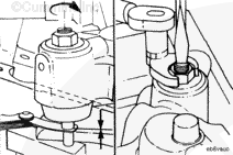
Place the STC tappet adjusting tool, Part Number 3823348, or equivalent, on the upper surface of the STC injector top-cap. Rotate the tool around the tappet until the tool’s locating pin is inserted into one of the four holes in the top of the tappet.
An overtightened setting on the injector adjusting screw will produce increased stress on the injector train and the camshaft injector lobe, which can result in engine damage.
Use torque wrench, Part Number 3376592, or equivalent, to tighten the adjusting screw while holding the tappet in the maximum upward position.
Two different methods for establishing valve lash clearance are described below. Either method can be used; however, the torque wrench method has proven to be the most concise. It eliminates the need to feel the drag on the feeler gauge.
Torque Wrench Method: Use the inch-pound torque wrench. Part Number 3376592, or equivalent, (normally used to set preload on top stop injectors), and tighten the adjusting screw.
After tightening the locknut to the correct torque value, check to make sure the feeler gauge will slide backward and forward between the crosshead and the rocker lever with only a slight drag.
If using the touch method, attempt to insert a feeler gauge that is 0.03 mm [0.001 in] thicker between the crosshead and the rocker lever pad. The valve lash is not correct when a thicker feeler gauge will fit.
After adjusting the valves, rotate the accessory drive and align the next valve set mark on the accessory drive pulley with the pointer on the gear cover.
NOTE: To obtain maximum brake operating efficiency and prevent engine damage by piston-to-valve contact, complete the following instructions carefully.
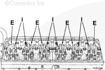
After adjusting the exhaust valves on the appropriate cylinder, insert a feeler gauge 0.38 mm [0.015 in] between the slave piston and the actuating pin in the crosshead.
Hello, I'm Jack, a diesel engine fan and a blogger. I write about how to fix and improve diesel engines, from cars to trucks to generators. I also review the newest models and innovations in the diesel market. If you are interested in learning more about diesel engines, check out my blog and leave your feedback.
View all posts by Jack


 WARNING


 CAUTION
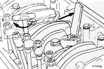

;)
;)
;)
;)
;)
;)
;)
;)
;)
;)
;)
;)
;)
;)
;)
;)
;)
;)
;)
;)
;)
;)
;)
;)
;)
;)
;)
;)
;)
;)
;)
;)
;)
;)
;)
;)
;)
;)
;)
;)
;)
;)
;)
;)
;)
;)
;)
;)
;)
;)
;)
;)
;)
;)
;)
;)
;)
;)
;)
;)
;)
;)
;)
;)
;)
;)
;)
;)
;)
;)
;)
;)
;)
;)
;)
;)
;)
;)
;)
;)
;)
;)
;)
;)
;)
;)
;)
;)
;)
;)
;)
;)