|
Swivel-Foot Rocker Lever Design Features
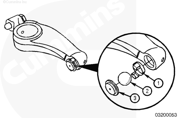
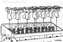
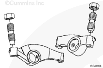
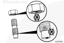
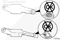
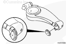
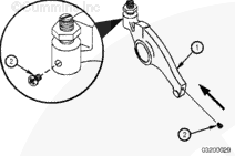
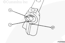
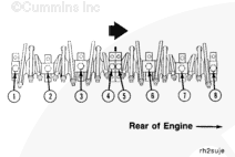
L10, M11, and ISM engines began using swivel-foot rocker levers in production engines starting with engine serial number (ESN) 34979852. The swivel-foot design, shown in Fig. 1 below, differs greatly from the previous inserted rocker lever design. Swivel-foot rocker levers have a ball-and-socket joint comprised of a retaining clip (1), steel ball bearing (2), and socket (3). The ball-and-socket joint reduces the scrubbing action of previous rocker lever designs and improves overhead component durability.
|
|
| Fig. 1 New Swivel-Foot Rocker Lever Design |
NOTE: Oil cross-drillings in both ends of the swivel-foot rocker levers are plugged with a steel ball bearing. Oil is fed to the swivel assembly through the retaining clip.
Replacing Inserted Rocker Levers and Heat-Treated Rocker Levers
Swivel-foot rocker levers obsolete and supersede both inserted rocker levers and heat-treated rocker levers.
When a swivel-foot rocker lever is used to replace an inserted or heat-treated rocker lever, the corresponding crosshead must be replaced. Swivel-foot rocker levers are backward compatible with inserted and heat-treated rocker levers and use the same valve lash setting procedure.
|
|
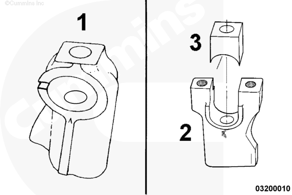
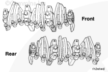
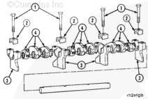
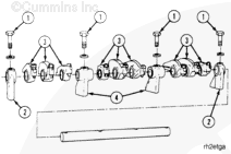
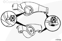
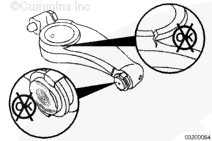
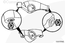
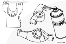
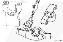
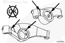
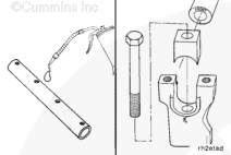
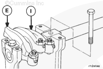
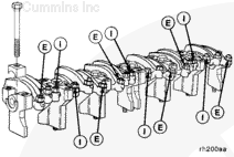
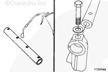
| Fig. 2 Aluminum (1) and Cast Iron (2 and 3) Rocker Lever Supports |
Rocker Lever Supports
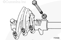
The M11 engine is built with one of two different types of rocker lever supports. Engines with the STC fuel system are built with aluminum supports (1). Engines built with the CELECT™ or CELECT™ Plus fuel system are built with a cast iron support (2) and retaining clamp (3).
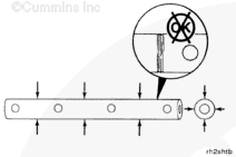
The removal and installation of the rocker lever assemblies in the engine are the same. However, on engines with the cast iron supports a piece of 1/4 inch key stock and four M10 – 1.50 x 25 capscrews are used to lift the assemblies in and out of the engine. All other removal, inspection, and installation procedures are the same.
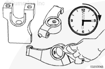
NOTE: Although the installation procedure is the same, the final torque value of the two types of supports is different. Both values are given.
The rocker levers and rocker lever shafts are the same regardless of which support the engine was built with.
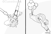
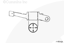
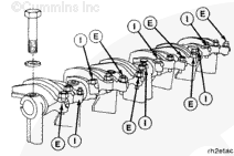
NOTE: Make certain that all swivel-foot rocker lever sockets remain in place within the retaining clip during assembly.
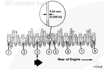
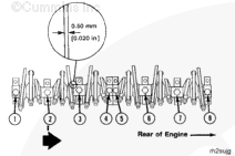
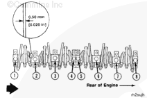
NOTE: Make certain that the feeler gauge is inserted fully between the socket and crosshead when setting the valve lash.
|


 WARNING


 CAUTION
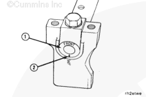

;)
;)
;)
;)
;)
;)
;)
;)
;)
;)
;)
;)
;)
;)
;)
;)
;)
;)
;)
;)
;)
;)
;)
;)
;)
;)
;)
;)
;)
;)
;)
;)
;)
;)
;)
;)
;)
;)
;)
;)
;)
;)
;)
;)
;)
;)
;)
;)
;)
;)
;)
;)
;)
;)
;)
;)
;)
;)
;)
;)
;)
;)
;)
;)
;)
;)
;)
;)
;)
;)
;)
;)
;)
;)
;)
;)
;)
;)
;)
;)