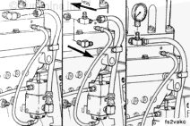
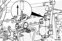
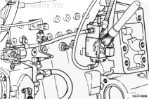
Disconnect the step timing control fuel pressure sensing line from the fuel inlet passage of the cylinder head. Plug the hole in the cylinder head with a pipe plug.
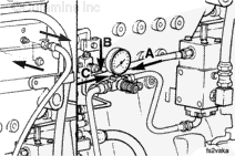
Connect the step timing control fuel pressure line (A) to the outlet side of the air pressure regulator.
Connect a 0-160 psi pressure gauge (B), to the air pressure regulator.
Connect a shop air pressure line (C), capable of providing 100 psi, to the inlet side of the regulator.
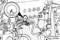
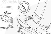
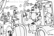
Operate the engine at idle. The oil pressure between the step timing control valve and the tappets must be at least 103 kPa [15 psi].
Because the oil pressure can be less than 103 kPa [15 psi] when the coolant temperature is above 49°C [120°F], these tests must be performed at temperatures below this level.
If the oil pressure will not reach 103 kPa [15 psi], the step timing control oil delivery system is not functioning properly. Perform the step timing control Oil Delivery System Diagnostics, Procedure 006-045.
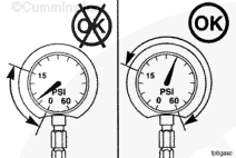
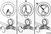
Slowly adjust the pressure regulator to increase the air pressure until the oil pressure drops below 55 kPa [8 psi]. Record the air pressure at this point. This is the upper shift-point (A).
The sound of the overhead will become quieter when the 55 to 69 kPa [8 to 10 psi] point is reached. This is the shift from ADVANCED to NORMAL timing.
Raise the air pressure at least 103 kPa [15 psi] above the upper shift-point then slowly begin to lower it. Record the air pressure at which the oil pressure raises above 55 kPa [8 psi]. This is the lower shift-point (B).
NOTE: The lower shift-point is the shift from NORMAL to ADVANCED timing. The overhead will go from quiet to noisy. This pressure must be lower than the upper shift-point. If it is not , repair or replace the step timing control valve.
Compare the shift-point values to those specified for the valve. If the values are not within these specifications listed, recalibrate the step timing control valve.
NOTE: Some step timing control valves do not have an adjusting screw. If the calibration is not within specifications, the valve must be removed and repaired or replaced.
Step Timing Control Valve Calibration Data
kPa
psi
Upper Shift Point
125
MIN
18
193
MAX
28
Lower Shift Point
Not more than 34 kPa [5 psi] below the upper shift point.
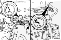
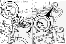
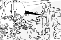
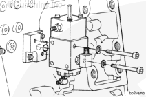
Use an Allen wrench to turn the step timing control valve adjusting screw. Turn the screw in a clockwise direction to raise the step timing control valve upper shift-point. Turn the screw in a counterclockwise direction to lower the upper shift-point.
Always start with the air pressure at 0 psi before checking the upper shift-point (A). Always raise the air pressure to at least 103 kPa [15 psi] above the upper shift-point (A) before checking the lower shift-point (B).
After adjusting the screw, repeat the step timing control shift-point check procedure.
Repeat the calibration and check procedure until the shift-points are within the set values listed in the table. If the valve cannot be calibrated to these specifications, replace it.
Step Timing Control Valve Calibration Data
kPa
psi
Upper Shift Point
125
MIN
18
193
MAX
28
Lower Shift Point
Not more than 34 kPa [5 psi] below the upper shift point.
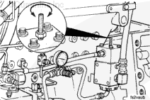
Remove the two capscrews which hold the step timing control valve to the mounting plate.
Remove the step timing control valve seal ring.
If installing an electronic step timing control valve, remove and save the 90 degree check valve fitting and save for use on the electronic step timing control valve.
When using solvents, acids or alkaline materials for cleaning, follow the manufacturer’s recommendations for use. Wear goggles and protective clothing to avoid personal injury.
WARNING
Wear appropriate eye and face protection when using compressed air. Flying debris and dirt can cause personal injury.
Plug all openings to prevent dirt from entering the valve.
Use a solvent that will not harm aluminum. Clean the outside of the valve and all the removed parts. Dry with compressed air.
Hello, I'm Jack, a diesel engine fan and a blogger. I write about how to fix and improve diesel engines, from cars to trucks to generators. I also review the newest models and innovations in the diesel market. If you are interested in learning more about diesel engines, check out my blog and leave your feedback.
View all posts by Jack


 WARNING
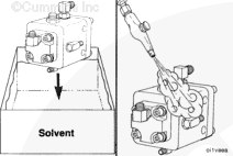

;)
;)
;)
;)
;)
;)
;)
;)
;)
;)
;)
;)
;)
;)
;)
;)
;)
;)
;)
;)
;)
;)
;)
;)
;)
;)
;)
;)
;)
;)
;)
;)
;)
;)