M11 Series – Service Manual – 010-033   Turbocharger

Remove

TOC

Remove the intake and exhaust pipes from the turbocharger.

SMALL | MEDIUM | LARGE


Remove the oil supply line from the turbocharger.

SMALL | MEDIUM | LARGE


Remove the oil drain line from the turbocharger.

SMALL | MEDIUM | LARGE


NOTE: Some engine applications use water-cooled turbochargers.

If a water-cooled turbocharger is used, drain the cooling system, and remove the water supply and return lines from the turbocharger.

 
SMALL | MEDIUM | LARGE


Remove the v-band clamp, discharge elbow, and o-ring from the turbocharger compressor discharge outlet.

Remove the four turbocharger mounting nuts.

Remove the turbocharger and gasket.

SMALL | MEDIUM | LARGE
   

Clean and Inspect for Reuse

TOC

Clean the turbocharger and exhaust manifold gasket surfaces.

SMALL | MEDIUM | LARGE


Inspect the turbocharger and exhaust manifold gasket surfaces, and mounting studs for cracks or damage.

SMALL | MEDIUM | LARGE


 CAUTION 

A charge air cooler failure can cause progressive damage to the turbine housing.

Inspect the turbine and compressor housings.

If cracks that go all the way through the outer walls are found, the housing must be replaced.

If the turbine housing is damaged, check the charge air cooler. Refer to Procedure 010-027.

SMALL | MEDIUM | LARGE


Cracks in the mounting flange longer than 15 mm [0.6-in] are not acceptable.

SMALL | MEDIUM | LARGE


Cracks of any length that reach mounting holes are not acceptable.

SMALL | MEDIUM | LARGE


Two cracks must be separated by at least 6.4-mm [0.25-in].

SMALL | MEDIUM | LARGE


Cracks of any length that extend through the divider are acceptable only if they are separated by at least 12.5-mm [0.50-in].

SMALL | MEDIUM | LARGE


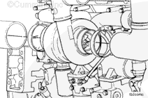
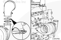
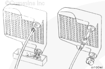
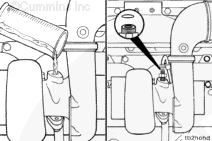
If the engine experiences a turbocharger failure or where oil or debris are put into the charge air system, the charge air system must be inspected and cleaned. Refer to Procedures 010-027 and 010-023.

SMALL | MEDIUM | LARGE
   

Install

TOC

NOTE: The torque values given have been established using anti-seize compound as a lubricant.

Apply a film of high temperature anti-seize compound to the turbocharger mounting studs.

Use a new gasket and install the turbocharger.

Install and tighten the four mounting nuts.

Torque Value:  61  n.m  [45 ft-lb]

SMALL | MEDIUM | LARGE


Install the discharge elbow, v-band clamp, and new o-ring seal on the turbocharger compressor discharge outlet.

Tighten the clamp.

Torque Value:  8  n.m  [75 in-lb]

SMALL | MEDIUM | LARGE


NOTE: Some engine applications use water-cooled turbochargers.

If a water-cooled turbocharger is used, install the water supply and return lines to the turbocharger.

 
SMALL | MEDIUM | LARGE


Install and tighten the turbocharger oil drain line.

Torque Value:  27  n.m  [20 ft-lb]

SMALL | MEDIUM | LARGE


Pour 50 to 60 cc [2.0 to 3.0 ounces] of clean 15W-40 engine oil in the turbocharger oil supply line fitting.

Install and tighten the turbocharger oil supply line.

Torque Value:   20  n.m  [15 ft-lb]

SMALL | MEDIUM | LARGE


Install the intake pipe and tighten the clamp.

Install the exhaust pipe and tighten the clamp.

Torque Value:  8  n.m  [72 in-lb]

SMALL | MEDIUM | LARGE


If a water-cooled turbocharger is used, fill the cooling system. Refer to Procedure 008-018.

Operate the engine and check for air leaks.

SMALL | MEDIUM | LARGE
   

Check for Correct Component

TOC

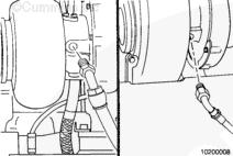
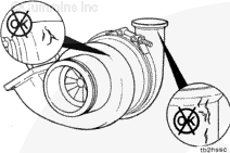
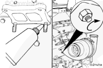
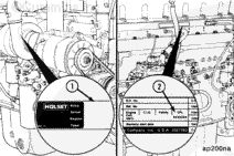
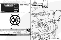
Compare the assembly number (1) on the turbocharger data tag with the turbocharger specified in the engine control parts list (CPL) number (2) listed on the engine dataplate.

SMALL | MEDIUM | LARGE


If the correct turbocharger was not installed, remove it, and install the correct turbocharger.

SMALL | MEDIUM | LARGE
Last Modified:  09-Dec-2004