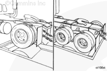
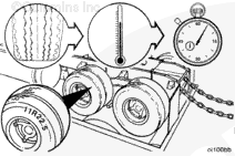
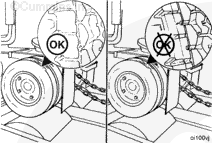
Low-profile radial tires are more sensitive to heat than bias ply tires. Excessive operating time at full load can damage tires due to overheating. Check the tire manufacturer’s recommendations for the maximum allowable chassis dynamometer operating time.
Check the engine coolant level to be sure it is filled to the proper level.
WARNING
Check the coolant level only when the engine is stopped. Wait until the coolant temperature is below 50°C [120°F] before removing the pressure cap. Failure to do so can cause personal injury from heated coolant spray.
CAUTION
Do not add cold coolant to a hot engine. This can cause engine casting damage. Allow the engine to cool to below 50°C [120°F] before adding coolant.
NOTE: Use a known source of “good” quality No. 2 diesel fuel. This is very important since No. 1 diesel fuels, along with most other alternate fuels, are lighter (lower specific gravity, higher API gravity) than No. 2 diesel fuel. The lighter the fuel, the lower the energy content (BTU) per gallon (liter, etc.).
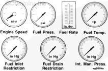
To properly monitor engine performance, record the following parameters. To limit dynamometer operating time, instrument the engine to make as many checks as possible.
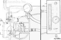
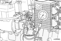
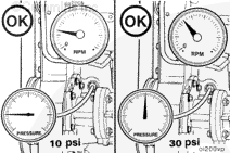
Measure the fuel pressure. Install the pressure gauge, Part Number ST-435-6, or the pressure gauge in the fuel measuring device, Part Number 3376375, to the fitting on the fuel shutoff valve.
NOTE: Pressure gauge, Part Number ST-435-6, is included with snap rail pressure gauge, Part Number 3375932.
Use fuel measuring device, Part Number 3376375, to measure the rate of fuel consumption. For more information, refer to “Engine Testing – General Information”.
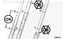
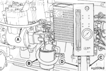
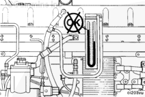
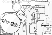
Install the fuel measuring device as follows:
The fuel return hose from the engine to the fuel measuring device (A).
The fuel inlet hose to the fuel filter inlet (B).
The return hose from the device (C) to the fuel tank.
The fuel inlet hose to the device from the fuel tank suction line (D).
NOTE: Adjust the fuel rate to compensate for temperature variation if required.
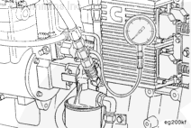
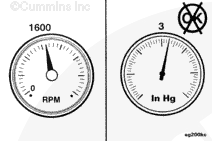
Measure the fuel inlet restriction. Install a vacuum gauge, Part Number ST-434, between the fuel filter and the gear pump inlet.
NOTE: Do not measure fuel inlet restriction with the fuel measuring device installed. This will not measure the inlet restriction of the vehicle’s supply plumbing.
Use Pressure Gauge, Part Number ST-1273, to measure fuel drain line restriction.
NOTE: Do not measure fuel drain line restriction with the fuel measuring device installed. This will not measure the drain line restriction of the vehicle’s return plumbing.
Intake Manifold Air Temperature Control – Chassis Dynamometer test
When operating an engine on a chassis dynamometer, follow these steps for best results and safe operation.
For CELECT™ and CELECT™ Plus engines
Lock the cooling fan in the “ON” mode. This can be done by installing a jumper across the temperature switch, or by supplying shop air to the control valve. Refer to the fan drive manufacturer for the recommended procedure.
Monitor the intake manifold air temperature using INSITE™ in the monitor mode, or install Fluke digital thermometer, Part Number 3822666, and thermocouple wire kit, Part Number 3822988, into the intake manifold.
The intake manifold air temperature must not exceed the maximum allowable temperature. The engine protection system will disrupt performance if the temperatures exceeds this level. Maintain intake manifold air temperature at the nominal level or below during chassis dynamometer operation.
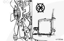
Lock the cooling fan in the “ON” mode. This can be done by installing a jumper across the temperature switch or by supplying shop air to the control valve. Refer to the fan drive manufacturer for the recommended procedure.
Remove any obstructions to the air flow across the radiator such as a winterfront. Manually lock the shutters in the “OPEN” position, if equipped.
Install a Fluke digital thermometer, Part Number 3822666, and attach thermocouple wire kit, Part Number 3822988, into the intake manifold. Monitor the intake manifold temperature. The temperature must not exceed 77°C [170°F].
If the intake manifold temperature exceeds the above limits, shut off the engine. Allow the engine to cool.
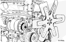
Inspect the radiator fins for obstructions to the air flow. Check the fan drive to make sure it is locked in the “ON” mode.
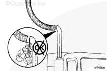
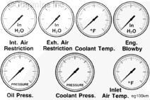
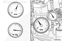
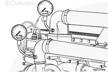
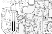
Measure the intake pressure drop across the charge air cooler, if applicable.
This test can be done with a mercury manometer or two separate gauges, Part Number ST-1273. If two gauges are being used, calibrate both gauges on a common pressure source to ensure consistency.
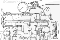
Install one pressure gauge, Part Number ST-1273, in the fitting in the turbocharger compressor outlet elbow. Install the other pressure gauge in the fitting in the intake manifold.
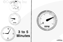
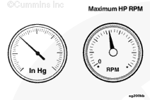
When measuring the pressure drop, operate a dynamometer at the rpm that delivers the maximum horsepower of engine tested. Engine speed will be 1600-1700 rpm on most engines.
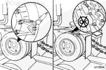
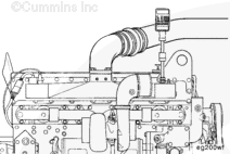
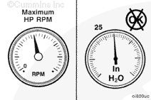
Measure the inlet air restriction. Install the vacuum gauge, Part Number ST-434, or a manometer in the intake air piping.
NOTE: The gauge adapter must be installed at a 90 degree angle to the air flow in a straight section of pipe at a minimum of one pipe diameter before the turbocharger.
Hello, I'm Jack, a diesel engine fan and a blogger. I write about how to fix and improve diesel engines, from cars to trucks to generators. I also review the newest models and innovations in the diesel market. If you are interested in learning more about diesel engines, check out my blog and leave your feedback.
View all posts by Jack
 CAUTION
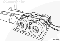


 WARNING
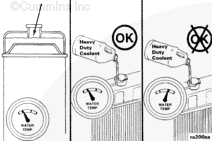


;)
;)
;)
;)
;)
;)
;)
;)
;)
;)
;)
;)
;)
;)
;)
;)
;)
;)
;)
;)
;)
;)
;)
;)
;)
;)
;)
;)
;)
;)
;)
;)
;)
;)
;)
;)
;)
;)
;)
;)
;)
;)
;)
;)
;)
;)
;)
;)
;)
;)
;)
;)
;)
;)
;)
;)
;)
;)
;)
;)
;)
;)
;)
;)
;)
;)