NOTE: Be sure the dynamometer capacity is sufficient to permit testing at 100 percent of the engine rated horsepower. If the capacity is not enough, the testing procedure must be modified to the restrictions of the dynamometer.
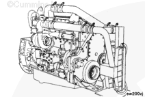
Use engine lifting fixture, Part Number 3822512, to install the engine to the test stand. Align and connect the dynamometer. Refer to the manufacturer’s instructions for aligning and testing the engine.
Refer to Service Bulletin 3666005, Dynamometer and Road Engine Testing, for detailed instructions on auxiliary aftercooling system attachment.
NOTE: Some engines are equipped with fittings used for Compuchek® testing sensors. The sensor probes used for Compuchek® and dynamometer testing are not compatible. If the same location is used, remove the Compuchek® fitting and install adapters for the dynamometer sensor.
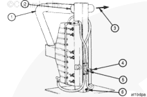
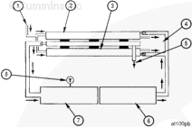
The use of a remote aftercooler is mandatory whenever a Cummins CAC engine is attached to an engine dynamometer for the purpose of engine run-in, performance testing and engine diagnostics. Do not attempt to run a Cummins CAC engine without any means of controlling the intake manifold air temperature. Service tool, Part Number 3823978, utilizes twin aftercooler assemblies arranged for parallel air and water flow to cool the intake air to acceptable levels.
The parallel air flow circuit heat exchangers provide optimum performance by delivering air to the intake manifold at temperatures no higher than 66°C [150°F], and with less than the maximum allowable intake air pressure drop (102 mm Hg [4 in Hg]).
The remote aftercooler removes energy from the intake air which is compressed and heated by the turbocharger to temperatures as high as 210°C [410°F] then cooled to temperatures of 66°C [150°F] using city water at 16°C [60°F].
Water from a city tap line flows to the aftercoolers via a one inch I.D. neoprene hose. Testing has shown that 12 gallon per minute (GPM) city water flow is required (6 GPM per aftercooler core) to adequately cool the intake air. A typical garden hose is not suitable for this flow due to the excessive restriction. A low restriction ball type or gate valve is suitable for the operation provided the required flow rates are obtained.
Water returns to the drain or reservoir from the aftercoolers via a one inch I.D. hose. A low restriction gate valve or ball valve must be placed on the drain line(s) to allow regulation of the water flow through the aftercoolers. This enables one to maintain optimum intake air temperature during the test or run-in procedure.
The condensate that will develop, as the intake air is cooled in the remote aftercooler, is allowed to drain at all times through a hole at the bottom of the tubular steel manifold between the aftercoolers. This fitting must remain unobstructed throughout each use of the aftercoolers.
NOTE: Some air flow will escape through the condensate drain opening, but it is insignificant compared to the total air flow.
The air flow piping requires 4 inch I.D. aluminized steel piping. The flow circuit must have as few bends as possible maximizing the length of straight sections. However, when bends are required, use long elbows. Do not use square elbows, or anything that changes the air flow direction quickly. To reduce intake air restriction, air flow direction changes must occur gradually.
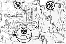
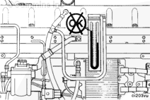
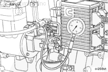
During engine test, monitor the pressure drop through the remote aftercooler. Install one end of a manometer to the Compuchek fitting in the turbocharger compressor outlet elbow. Install the other end of the manometer to the Compuchek™ fitting in the intake manifold. Although less accurate than a manometer, two individually calibrated press (in Hg) gauges can be used to monitor pressure drop.
The pressure drop between these two locations must not be greater than 152 mm Hg [6 in Hg]. If the pressure drop is greater than 152 mm [6 in Hg], check the remote aftercoolers and air flow piping for plugging. Clean and replace if necessary.
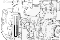
During engine test, also monitor intake manifold temperature. Install a thermocouple (Fluke) in the 1/2 inch pipe tap in the intake manifold. The intake air heats up as it passes through the intake manifold so the temperature must be measured as close to the intake manifold elbow as possible.
If the intake manifold temperature exceeds 66°C [150°F] during the test, make sure that there is an ample supply of clean cool water flowing through the aftercoolers. Under no circumstances must the intake air temperature be allowed to exceed 77°C [170°F].
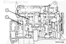
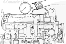
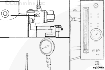
On STC engines, remove the pipe plug in the intake manifold just below the inlet air connection and install the intake manifold pressure gauge, Part Number ST-1273.
Install the lubricating oil pressure gauge, Part Number 3375275.
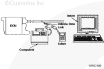
On CELECT™ and CELECT™ Plus engines, use a Cummins Electronic Service Tool to monitor the lubricating oil temperature.
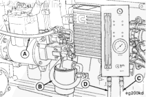
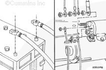
The Part Number 3376375, Fuel Measuring instrument, is used during the performance check to measure fuel consumption. For more details, refer to “Engine Testing – General Information”.
Install the fuel measuring device as follows:
The fuel return hose from the engine to the fuel measuring device (A).
The fuel inlet hose to the fuel filter inlet (B).
The return hose from the device (C) to the fuel tank.
The fuel inlet hose to the device from the fuel tank suction line (D).
NOTE: Adjust fuel rate to compensate for temperature variation if required. The fuel temperature must be between 15.5°C and 48.9°C [60°F and 120°F] for accurate measurement.
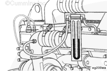
Measure the fuel inlet restriction. Install a vacuum gauge, Part Number ST-434, between the fuel filter and the gear pump inlet.
NOTE: Do not measure fuel inlet restriction with the fuel measuring device installed. This will not measure the inlet restriction of the vehicle’s supply plumbing.
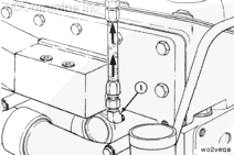
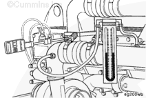
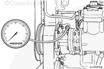
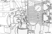
Measure the fuel pressure. Install the pressure gauge, Part Number ST-435-6, or the pressure gauge in the fuel measuring device, Part Number 3376375, to the Compucheck® fitting on the fuel shutoff valve.
NOTE: Pressure gauge, Part Number ST-435-6, is included with snap rail pressure gauge, Part Number 3375932.
Use pressure gauge, Part Number ST-1273, to measure fuel drain line restriction.
NOTE: Do not measure fuel drain line restriction with the fuel measuring device installed. This will not measure the drain line restriction of the vehicle’s return plumbing.
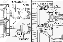
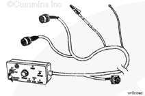
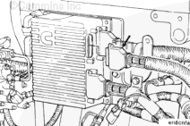
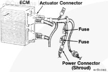
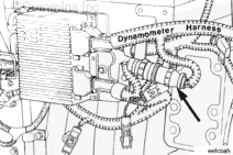
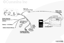
CELECT™ and CELECT™ Plus engines which are run on an engine dynamometer require that the engine harness be installed, and connected to the engine. Additionally, a special engine dynamometer version of the OEM wiring harness and throttle control must be installed.
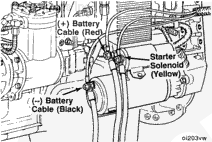
Connect the dynamometer test OEM wiring harness starter solenoid lead (yellow) to the starter solenoid. Connect the ground lead (black) to the starter or battery negative or ground side. Connect the positive 12 VDC power lead (red) to either the starter or battery positive (+12 VDC) side.
Hello, I'm Jack, a diesel engine fan and a blogger. I write about how to fix and improve diesel engines, from cars to trucks to generators. I also review the newest models and innovations in the diesel market. If you are interested in learning more about diesel engines, check out my blog and leave your feedback.
View all posts by Jack


;)
;)
;)
;)
;)
;)
;)
;)
;)
;)
;)
;)
;)
;)
;)
;)
;)
;)
;)
;)
;)
;)
;)
;)
;)
;)
;)
;)
;)
;)
;)
;)
;)
;)
;)
;)
;)
;)
;)
;)
;)
;)
;)
;)
;)
;)
;)
;)
;)
;)
;)
;)
;)
;)
;)
;)
;)
;)